SHIMPO DT-601CG User Manual
Page 9
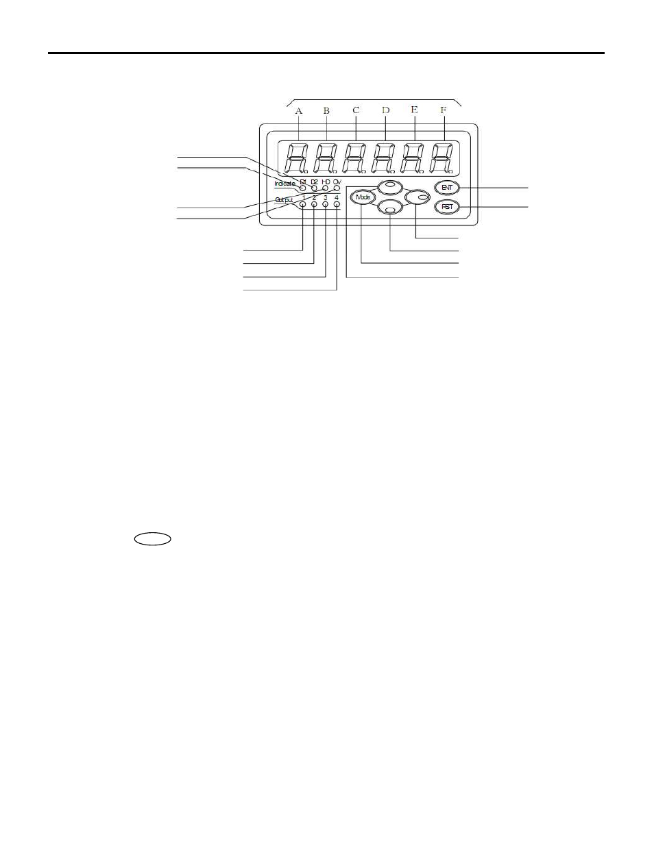
4. NAMES AND FUNCTIONS OF EACH PARTS IN THE FRONT.
(1) Display (A to F)
While measuring
: Indicate the measured value of Display 1(D1) or Display 2(D2)
While setting
: While setting modes, Display A and B indicate mode number and C to F indicate
setting value
: While setting preset value, display indicates current value
: While setting the display offset value, display indicates current value
(2)-(5) OUT1- 4 Alarm output LED
Synchronically flash when the OUT1 to 4's alarm was output
(6) Overscale LED
Flash when the value exceed 999999 or below -99999.
(7) Hold LED
F
lash when there is external input (shunt terminal block #2 and #3)
(8) Mode Key
While turning on
: TEST mode is activated when power is turned on while pressing this key
(To escape from TEST mode, turn off the power)
While measuring
: Mode setting is activated when Shift key is pressed more than 2seconds
while pressing this key.
: Preset value setting is activated when the key is pressed more than 2seconds.
: Display offset value setting is activated when Up key is pressed more than
2seconds while pressing this key.
While setting
: Mode number (Display A, B) can be changed over
: While setting preset value, preset number (PRESET A to B) can be switched over.
(1)Display(Red)
(2)Alarm output: OUT1(Red)
(3)Alarm output: OUT2(Red)
(4)Alarm output: OUT3(Red)
(5)Alarm output: OUT4(Red)
(15)Display2 LED (Green)
(14)Display1 LED (Green)
(7)Hold LED(Green)
(6)Overscale LED(Green)
(12)Entre key
(13)Reset key
(9)Shift key
(11)Down key
(8)Mode key
(10)Up key
Mode
P7