SHIMPO FG-3000 User Manual
Nidec-shimpo instruments, Fg-3000 digital force gauge operation manual
The new FG-3000 Series digital force gauges are the
choice for simple, cost-effective tension and compres-
sion testing.Combining one of the most compact hous-
ings, yet maintaining a large back-lit LCD, these units
were designed to fit perfectly in the hand for ease of
use. The multi-language FG-3000’s provide menu pro-
gramming for intuitive set-up of the instrument to your
desired requirements. Three modes of operation are
selectable: Track mode displays live readings, Peak
mode records the maximum reading sensed during the
test, and Pre-set mode which activates user defined
high and low limit set points. The programmable lim-
its provide a quick visual and audible indication if a
test passes or fails. In addition, a comparator output
enables integration of the instrument into your qual-
ity system for repetitive testing such as on production
lines.
The display graphics facilitate user comprehension
and operation. An analog bar graph provides perspec-
tive of current reading in comparison to the full scale
range. Pass/Fail icons provide an instant response of
the testing outcome while a storage symbol acknowl-
edges when a reading is logged. A menu-selectable
display orientation streamlines switching from push to
pull testing for portable or test stand applications.
FG-3000 Digital Force Gauge
Operation Manual
NIDEC-SHIMPO INSTRUMENTS
Operators should wear protection such as a mask and gloves in case
pieces or components break away from the unit under test.
Whether the unit is ON or OFF, DO NOT exceed the capacity of the
gauge. NEVER exceed 150% of the rated capacity, or the load cell will
be damaged. At 110% of the rated capacity, the display will flash a
warning.
When mounting FG-3000 Series Digital Force Gauges, use M6 mount-
ing screws with a maximum insertion depth of 7 mm into the gauge.
Hand tighten mounting screws, DO NOT use tools. Do not use dam-
aged clamp.
Measure in line tension and compression forces only. DO NOT attempt
to measure forces at an angle to the measuring shaft – damage to load
cell and/or shaft may result.
Do not attempt to repair or alter this instrument. Warranty will be voided
and damage to the unit may result.
Use and store within the stated temperature and humidity ranges, or
damage and failure may result.
When using adapter measuring heads, do not use tools. Hand tighten
only.
SPECIFICATIONS
Accuracy: ± 0.3% F.S.
Selectable Units: N, kgf, ozf, and lbf. (Depending on Range)
Overload Capacity: 150% of F.S. (LCD flashes beyond 110% of
F.S.)
Measurement Method: Peak, Track, Preset
Data Sampling Rate: 1000 Hz
Display: 160*128 dot matrix LCD with Backlight
Display Update Rate: 10 times/second
Resolution: (See chart)
Memory: 500 data
Set Point: Programmable high and low limits in Preset Mode
Battery Indicator: Display flashes battery icon when battery is
low
Power: 3.6VDC 800mAH Ni-MH rechargeable batteries
Battery Life: Approximately 16 hours continuous use per full
charge
Charger / Adaptor: Universal USB/BM charger, Input: 110 ~
240VAC
Temperature Effects: <0.054% per °F (0.03% FS per °C)
Outputs: USB, RS-232; High & Low Limit NPN’s
Operating Temperature: 14 to 104°F (-10 to 40°C)
Storage Relative Humidity: 20 to 80%
Housing: Aluminum
Storage Temperature: -4 to 122°F (-20 to 50°C)
Oper. Relative Humidity: 5 to 95%
Dimensions: 5.5 x 2.8 x 1.4” (140 x 71 x 35.5 mm)
Product Weight: 0.9 lb (0.4 kg)
Package Weight:
2.25 lb (1 kg)
Warranty: 1 year
Included Accessories: AC Adaptor/Charger, USB cable, calibra-
tion cert., 6 attachments: hook, flat tip, conical tip, chisel tip,
notched tip, extension shaft.
1
4
3
5
6
7
10
8
9
2
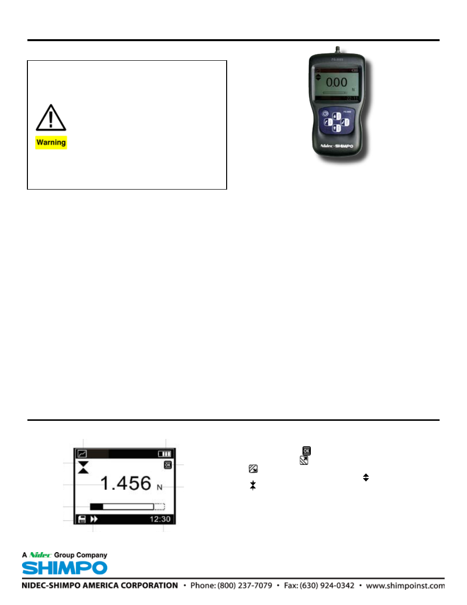
LCD Screen
1. Battery icon: Battery level or charging status. Flashes when
gauge needs to be recharged.
2. OK/OV Indicator: Measured value between low limit
and upper limit; Value over upper limit
Value between lower limit and 75% of lower limit
3. Force icon: Indicates force direction. Tension
Compression
4. Test mode icon: Three measurement modes: Track, Peak
and Preset
5. Current meaured value
6. Analog bar: Indicates current position within full scale. When
the bar enters the area enclosed by the dotted line, it means
full scale capacity is exceeded and overload.
7. Storage icon: Indicates data is being saved.
8. System time
9. Units Indicator: Selected engineering unit.
10. Data Transmission icon