SHIMPO DT-601CG User Manual
Page 16
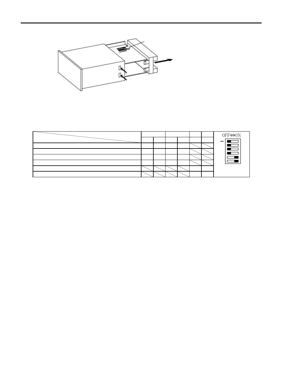
8. SETTING UP THE DIP SWITCH
Fig. 20
Setting up the DIP Switch
Dip switch setting can switch mode from input respond frequency, NPN open collector pulse input
and electric pulse input
Table 1
B.IN A.IN
1
2
3
4
5
6
ON OFF OFF ON
OFF ON
ON OFF
OFF OFF OFF OFF
OFF OFF OFF OFF
ON
ON
OFF OFF
(1) Dip switch can be found from the slit on the right side's corner of the main body. (Ref. Fig. 20)
If it is not convenient to set, pull out the PCB from the case and do the setting.
(2) Following three kinds of input type has to be used with the factory preset mode;
Sinusoidal input(V3),sine curve input(N) and line receiver input(L1, L2).
(3) For 90°phase contrast input (RE)type,
make sure to keep the factory preset mode (HI) for both A/B inout for respond frequency.
(4) Dip switch setting must be done by the combinations shown on the above chart.
The usage of the combination which is not indicated above might cause some error.
black shows the
setting
NPN Open Collector Pulse Input
Voltage Pulse Input
B. IN
A. IN
max. link ejecting frequency 0.01Hz-50Hz (LOW)
max. link ejecting frequency 0.01Hz-1kHz (MID)
max. link ejecting frequency 0.01Hz-10kHz (HI)
max. link ejecting frequency 0.01Hz-120kHz (OP.)
DIP SWITCH
Push the 4 tabs at the side of case
and pull the PCB backwords
Push the four hooks
P14