Edwards Signaling 2400 Series User Manual
Page 58
50
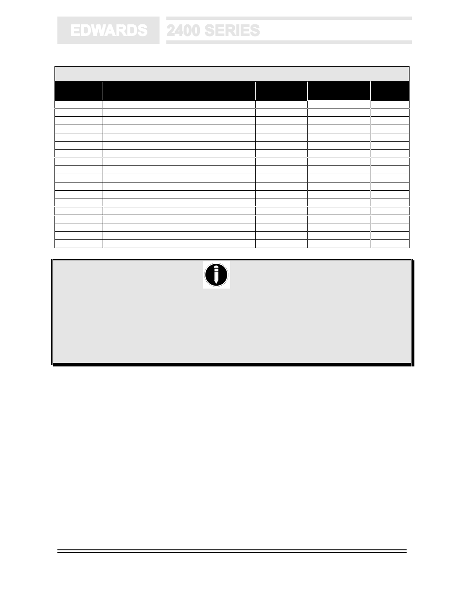
Table 10.11 - ULC Device & Panel Compatibility - Initiating Devices
Cat. #
Description
UL
Identifier
Max. # Devices
per IDC Zone
Options
291C
135ºF (57ºC) Heat Detector
001
50
1
292C
197ºF (92ºC) Heat Detector
001
50
1
293C
135ºF (57ºC) Heat Detector
001
50
1
294C
197ºF (92ºC) Heat Detector
001
50
1
5956A
Fire Alarm Indicator - LED
NA
NA
6249C
Ionization Smoke Detector c/w Base
001
50
3,5
6250C
Ionization Smoke Detector
001
50
1,5
6260A-100
Duct Detector/Sensor Housing (housing only)
NA
NA
6260C-005
Duct Detector Assembly, Low Velocity
NA
NA
6262A-001
Fire Alarm Indicator/Test Station
NA
NA
6264C-001
Ionization Detector, Duct
001
50
1,2,5
6264C-005
Ionization Detector, Duct, Low Velocity
001
50
1,2,5
6266C-001
Photoelectric Detector, Duct
001
30
1,2,5
6269C
Photoelectric Smoke Detector c/w Base
001
30
3,5
6269C-003
Photoelectric/Heat Detector c/w Base
001
30
3,5
6270C
Photoelectric Smoke Detector
001
30
1,5
6270C-003
Photoelectric/Heat Detector
001
30
1,5
6426A
Beam Smoke Detector - 4-wire
NA
NA
4
NOTES
1.
These detectors plug into the following base: Cat.# 6251B-001A. Compatibility ID for all bases is 001.
The Cat.# 5956A remote LED may also be used with these bases.
2.
These detectors are used with the following detector housings: Cat.# 6260A-100 and Cat.#6260C-005
duct detector assembly and fire alarm indicator/test station.
3.
The Cat.# 5956A remote LED may also be used with these bases.
4.
The Cat.# 6424A Beam Smoke Detector is powered from auxiliary power.
5.
Low impedance detectors. (Refer to Programming Section for proper operation.)
6.
High impedance detectors. (Refer to Programming Section for proper operation.)