AW Gear Meters EMO-3000 User Manual
Page 10
EMO‐3000
Operation and Programming Manual
9
15‐Position Connector
On channel cards manufactured after July 1993, an eight‐position DIP switch is used to set the cards’
channel number. This is only available if the EPROM has channel FF marked on it (default). Otherwise
the channel number is hard‐coded in the EPROM and the channel number is marked on the EPROM
label.
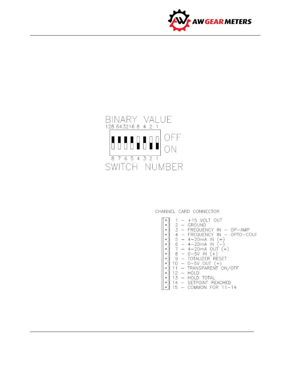
The channel number is a BINARY number. Switch #1 has a value of 1, #2 a value of 2, #3 a value of 4, #4
and value of 8, #5 a value of 16, and so on. Examples: to set the card to Channel 7, place switches #1, 2,
and 3 in the ON position (1+2+4 = 7). Set switch #2 and 4 to the ON position for Channel 10 (2+8 = 10). In
the example below, the channel number is set to 11 (1+2+8 = 11).
EMO‐3000 Card Pin Layout
PIN 1 External power supply. A jumper on the power supply card sets the voltage level (refer to
Appendix I). The options are 24 volts, 15 volts, or 5
volts. Default setting is 15 volts. This supply pin
delivers 25 mAmp per card.
PIN 2 This is the common ground for pins 1, 3, 4, 7,
8, 9, and 10. Ground the EMO‐3000 to the central
grounding point from this pin.
PIN 3 Secondary frequency input B. Use the input
for the secondary flow transmitter input in the Ratio
mode. Input is Op‐Amp isolated. A jumper sets the
voltage sensitivity for either 50mV, 1.75V, or 3.7V.
Default setting is for 1.75V (refer to Appendix H and
Q).