AW Gear Meters JVS-01UF MicroFlow User Manual
Microflow, Gear meter maintenance guide
AW Gear Meters Franksville, WI web:
www.awgearmeters.com
Tel: 262‐884‐9800 Fax: 262‐884‐9810 Email: awinfo@aw‐lake.com
REV. 07/09 JVS‐01UF.DOC
MicroFlow
™
Gear Meter Maintenance Guide
Cleaning, inspecting or repairing a JVS-01UF MicroFlow
™
Series gear meter
can be easily accomplished by following the procedures below.
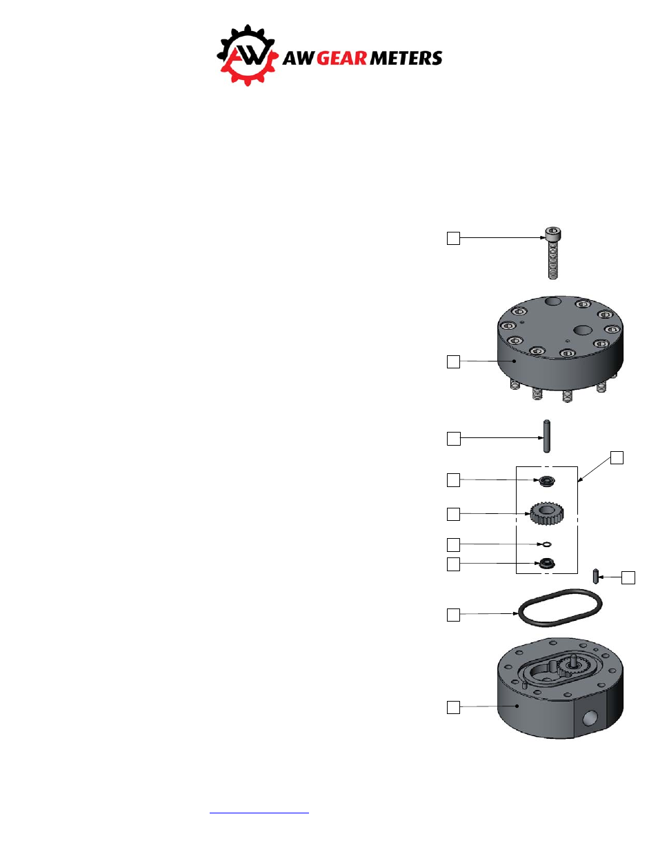
1. Remove the Sensor from the flow meter body Upper Housing (2).
2. Remove the M6 Bolts (1) using a 5mm hex key. Keep the 2 opposing
bolts near the Locating Pins (5) engaged by a few threads to avoid
stress on the shafts and the locating pins during housing separation.
Please note the orientation of the Upper and Lower housings with
respect to each other so that the meter is reassembled the same
way.
3. Holding the Upper Housing (2), gently tap on the top of the 2 opposing
bolt heads to separate the Upper Housing (2) from the Lower Housing
(7). Do NOT use chisels or screwdrivers to split and pry apart the
housings. This can cause damage to the meter bodies and meter
internal parts.
4. After separation, remove, clean and inspect the gear assemblies (4) and
shafts (3). Clean out the o-ring groove, shaft holes and meter cavity.
IMPORTANT: The gear assembly consists of two bearings (4a), the
Gear (4b), and a Bearing Spacer (4c). These parts are loosely fitted
and can fall out. These parts are matched together and careful
attention MUST be made to their orientation and location as they
MUST be replaced the exact way they were.
5. After cleaning all parts completely, the Gear Assemblies (4), Shafts (3)
and Locating Pins (5) can be reinserted. Check for free and easy
rotation of the gears.
6. Replace the O-Ring (6). 37)( o-rings should always be replaced. ).0
o-rings can be reused if they are not damaged.
7. During reassembly keep the meter housings as parallel as possible.
Make sure the housings are orientated the same way they were prior to
disassembly.
8. Replace the Bolts (1). Torque the bolts to 15Nm (11ft/lbs). Do not force
the meter housings together. Do NOT use a hammer or other such
device. Over tightening will not cause damage to the meter, but may
fatigue the bolts and/or restrict the operation if internal surfaces are not
completely clean.
9. After reassembly, gently blow air through the meter so the gears spin.
This should be clearly audible given a moderate background noise level.
10.
Clean any debris from the pickup hole before remounting the sensor to
the Upper Housing (2).
1
2
3
4
5
6
7
4a
4a
4b
4c