4 hardware configuration and wiring, 5 display/keyboard functions, Figure 2-2. cpu configuration – Condec DLR3110 User Manual
Page 8: Unit is in motion, Zero, Display
4
DLR3110 Rack Mount Digital Pressure Calibrator Manual
2.4
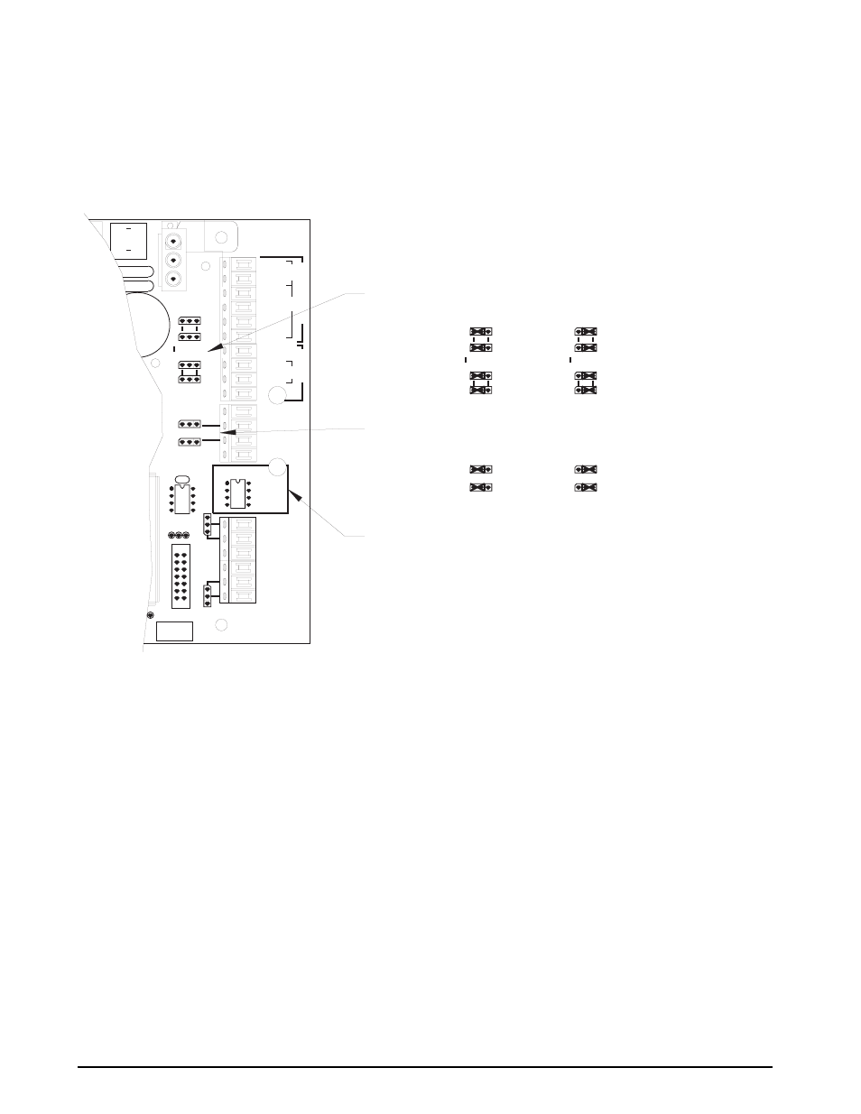
Hardware Configuration and Wiring
The CPU board in the DLR series has been designed for easy access to wiring and configuration of all available
inputs and outputs. In addition to easy access, the wire and configuration mapping provide clear labeling of all
input and output signals and the associated configurations of their device drivers.
Figure 2-2. CPU Configuration
NOTE: Unit is shipped previously set up and configured. For information on changing hardware configuration see
Section 5.11 on page 21.
2.5
Display/Keyboard Functions
See Figure 2-3 on page 5 for information on display and keyboard functions.
•
Six-digit LED display of the measured pressure (1).
•
Three annuciators: Two of the LEDs are used for indicating whether the unit is operating as a GAGE
pressure unit or as an absolute (ABS) pressure unit. The LED marked
P
indicates that the unit is in the
delta P display mode (2).
•
Eight character LED display for indicating the conversion units that the pressure data is currently being
displayed in. This display also scrolls prompting messages if corrective action is required or a problem
occurred in performing an operation (3).
For example, if attempting to perform a push to ZERO while the pressure data is in motion, the display
shows
Unit is in MOTION
.
•
In GAGE units, the
ZERO
function key (4) allows the indicator to be zeroed if it is within the limits
defined by the ZERO configuration.
•
DISPLAY
key (5). In the normal operating mode this key is used to select and view all active displays that
were enabled in the Configuration mode (i.e., Pressure data, MIN/MAX data, Freeze mode data, and
delta P display mode data).
THE PORT 1 INPUT SWITCH SELECTS FROM WHICH DEVICE THE SERIAL DATA IS RECEIVED
JUMPER POSITION
JUMPER POSITION
PORT 1 CONFIGURED FOR 20ma
CURRENT LOOP
PORT 1 CONFIGURED FOR RS232
PORT 1 CONFIGURED FOR RS485 OR
RS422 (RECEIVER)
PORT 1 CONFIGURED FOR RS485 OR
RS422 (TRANSMITTER)
JUMPER POSITION
SHOWN CONFIGURED AS INPUTS
SHOWN CONFIGURED AS OUTPUTS
TB1
P1 IN
GND
J2
TB2
S4
P1
F1
C1
C2
3
LO
10
HI
S8
S9
RS485
AB
20mA
TB3
1
S7
B
A
S6
RS422
RS232
3
OUT
S5
IN
14
REMOTE SENSING
U18
C38
S10
OFF
1
S3
E12
E10
E11
7
S2
8
1
J3
RETURN
SIG COM
20mA LOOP
P2
+OUT
-OUT
-IN
P1
+OUT
-OUT
+IN
OUTOUT
P2
RS232
P1
IN
OUT
I/O 1
I/O 2
+5V
-SIG
RS422
RS232
20mA
RS485
6
-SENSE
-EXC
+EXC
+SENSE
+SIG
1
RS232
RS422
S6
AB
S7
20mA
B
A
RS485
S9
S8
P1
P1
S8
S9
RS485
AB
20mA
S7
B
A
S6
RS422
RS232
IN
S5
OUT
S4
IN
S5
OUT
S4
TB1
S13
E8
-EXC
+EXC
KKR8924-[]
ASSEMBLY
CPU
DATE []
REV []
PORT 1 SERIAL INPUT SELECTION
SERIAL INPUT/OUTPUT SELECTION
INPUT/OUTPUT CONFIGURATION
JUMPER POSITION