0 maintenance and service, 1 troubleshooting, 2 maintenance and service procedures – Condec DLR3110 User Manual
Page 43: 1 panel/chassis removal and installation, Maintenance and service, Panel/chassis removal and installation
Maintenance and Service
39
7.0
Maintenance and Service
The following sections cover troubleshooting, maintenance and service procedures for the DLR3110.
7.1
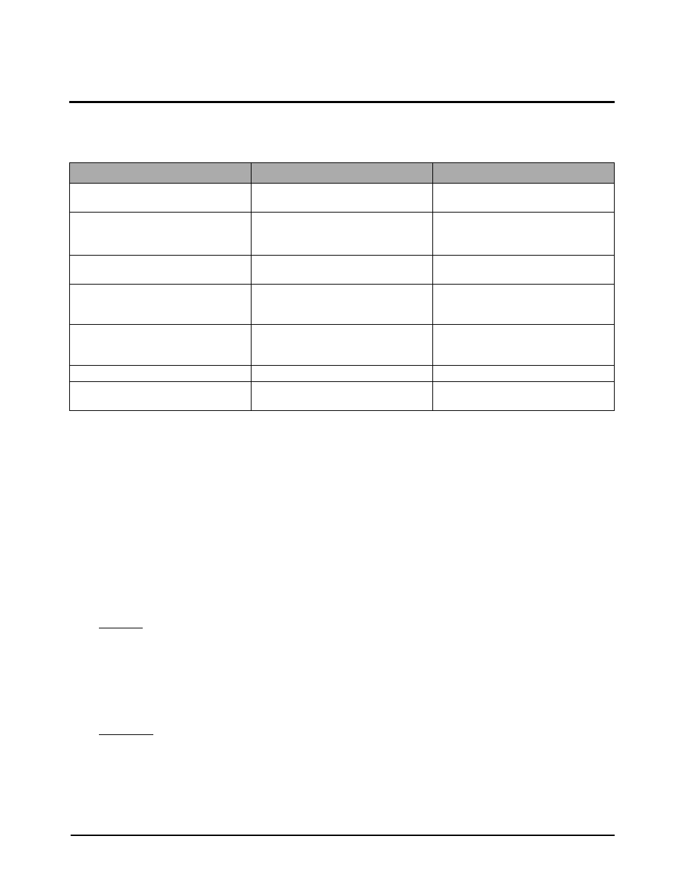
Troubleshooting
7.2
Maintenance and Service Procedures
This section outlines the mechanical and basic electrical repair procedures for the rack-mount pneumatic
pressure calibrator, model DLR3110. The repair procedures cover the major components and sub-assemblies that
are critical to the proper functioning of the calibrators and that need periodic maintenance over the life of the
unit. Only those persons who are formally trained as skilled technicians should attempt to repair these units. All
relevant safety precautions should be observed due to the presence of electrical components and high-pressure
components.
NOTE: Based on model, the following may give information on components that are not part of your DLR3110.
7.2.1
Panel/Chassis Removal and Installation
Removal
Tools required:
Phillips screwdriver
1. Vent system and remove input pressure source. Disconnect power cord, hoses, connectors, etc. from rear
of DLR3110. Remove from rack, if applicable, by grasping the handles located on the front of the unit
and gently set the rack-mount assembly on a bench top. It can be rested on the panel bottom and chassis
edge.
2. Loosen and remove the three screws (PN 14839) from rear and sides that secure the cover to the chassis.
Installation
Tools required:
Phillips screwdriver
1. Align mounting holes of cover with chassis and install three screws (PN 14839) from rear and sides that
secure the cover to the chassis.
2. Lift the panel and chassis by grasping the handles located on the front of the unit and re-install in rack, if
applicable. Connect input pressure source, power cord, hoses, connectors, to rear of DLR3110.
Symptom
Problem
Remedy
No lit display
Unit does not energize
Check fuse, check power source, check
power switch
Display slowly decreases over time
Leak in system
Check all compression and pipe fittings
with SNOOP
®
*
, bottle of liquid leak gas
detector (PN 64781)
*SNOOP
®
is a registered trademark of Swagelok.
Display does not respond when Vernier
knob is turned
No Vernier control
Readjust isolation valves on Orion;
replace O-ring on Vernier piston
Display increases or decreases when
INPUT (Pressure) or VENT valves are
closed
No Pressure or Vent control
Replace valve seats or o-rings in valves;
check valve needles
Unit will not stay in CAL, display shows
"-0L- -OVER-", or display reads a high
value @ zero PSIG
Transducer over-pressurized
Replace transducer
Display does not zero
Display does not zero
Perform a ZERO/SPAN calibration
Display shifts, is not steady
Transducer drifts or possible over
pressure
Replace transducer
Table 7-1. DLR3110 Troubleshooting