9 print and zero wiring configration example, Print and zero wiring configration example – Condec DLR3110 User Manual
Page 35
Configuration and Calibration
31
5.13.9
Print and Zero Wiring Configration Example
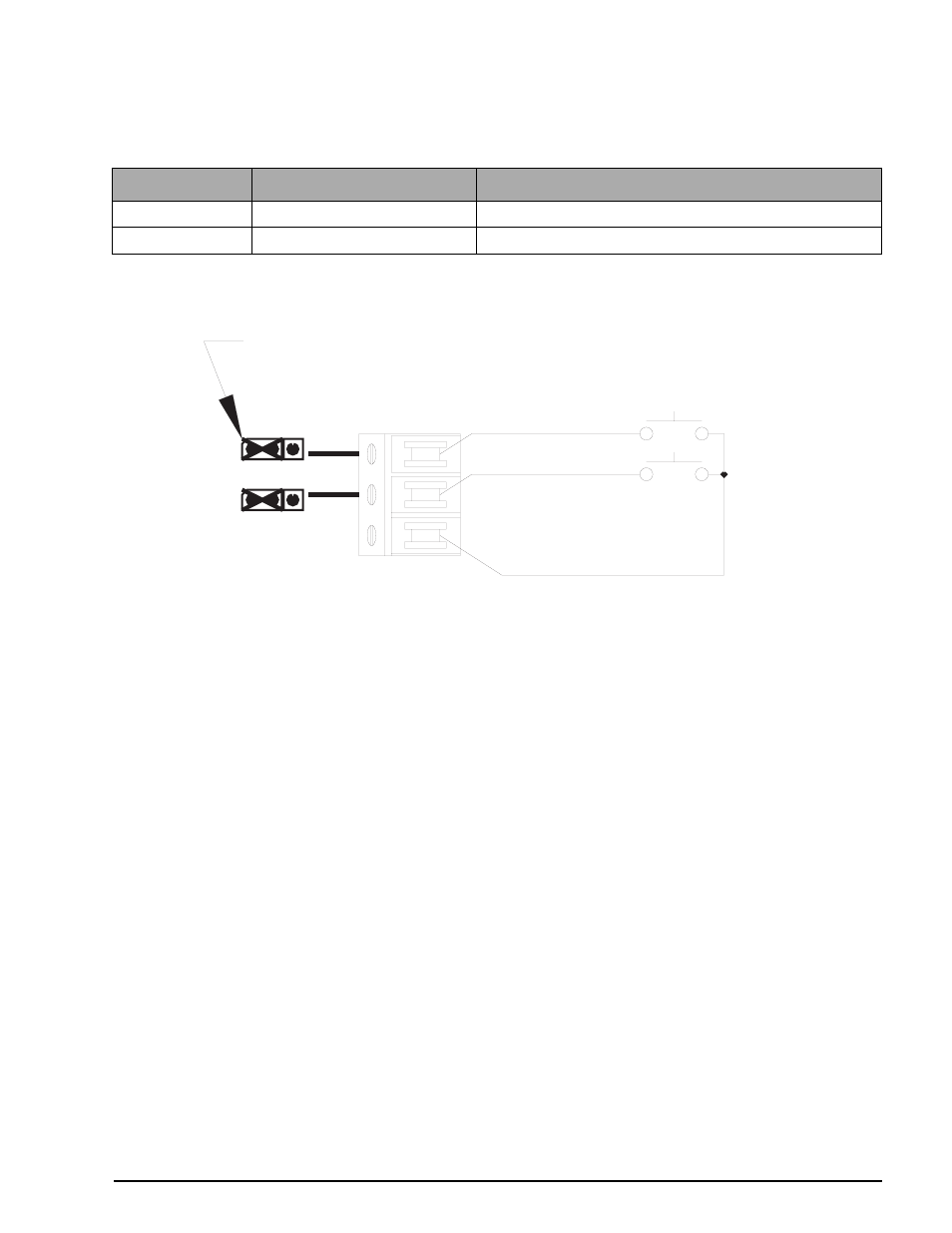
Table 5-21 illustrates a typical wiring configuration to operate the PRINT and ZERO commands remotely.
Figure 5-10. Remote Print and Zero Wiring Example
LED Display
Alpha-Numeric Display
Remarks
INPUT.1
ZERO
INPUT 1 assigned as a ZERO input
INPUT.2
INPUT 2 assigned as a PRINT input
Table 5-21. Wiring Configuration Example
TB2
S4
OUT
S5
IN
RETURN
I/O 1
I/O 2
(DIGITAL COMMON)
JUMPER PLUGS SHOWN ON S4 & S5 CONFIGURED AS AN INPUT
ZERO