7 modifying data, 8 span calibration points, 9 resetting span calibration points – Condec DLR3110 User Manual
Page 23
Configuration and Calibration
19
5.7
Modifying Data
Data values previously set are easily altered by pressing either of the horizontal arrow keys to enter the
modification mode. Upon entering the mode, the least significant digit
(LSD)
begins to flash. A flashing digit
indicates the current position in the data that can be changed. Press the
LEFT
or
RIGHT
arrow key to select a
desired position indicated by the flashing digit, then use the
UP
or
DOWN
arrow key to increment or decrement
the value of the selected digit. Once the new data value has been set, press the
ENTER
key to accept or the
CE
to
abort. If an abort is issued, the data reverts back to its former value. The display prompts with
ENTER
or
ABORT
accordingly.
5.8
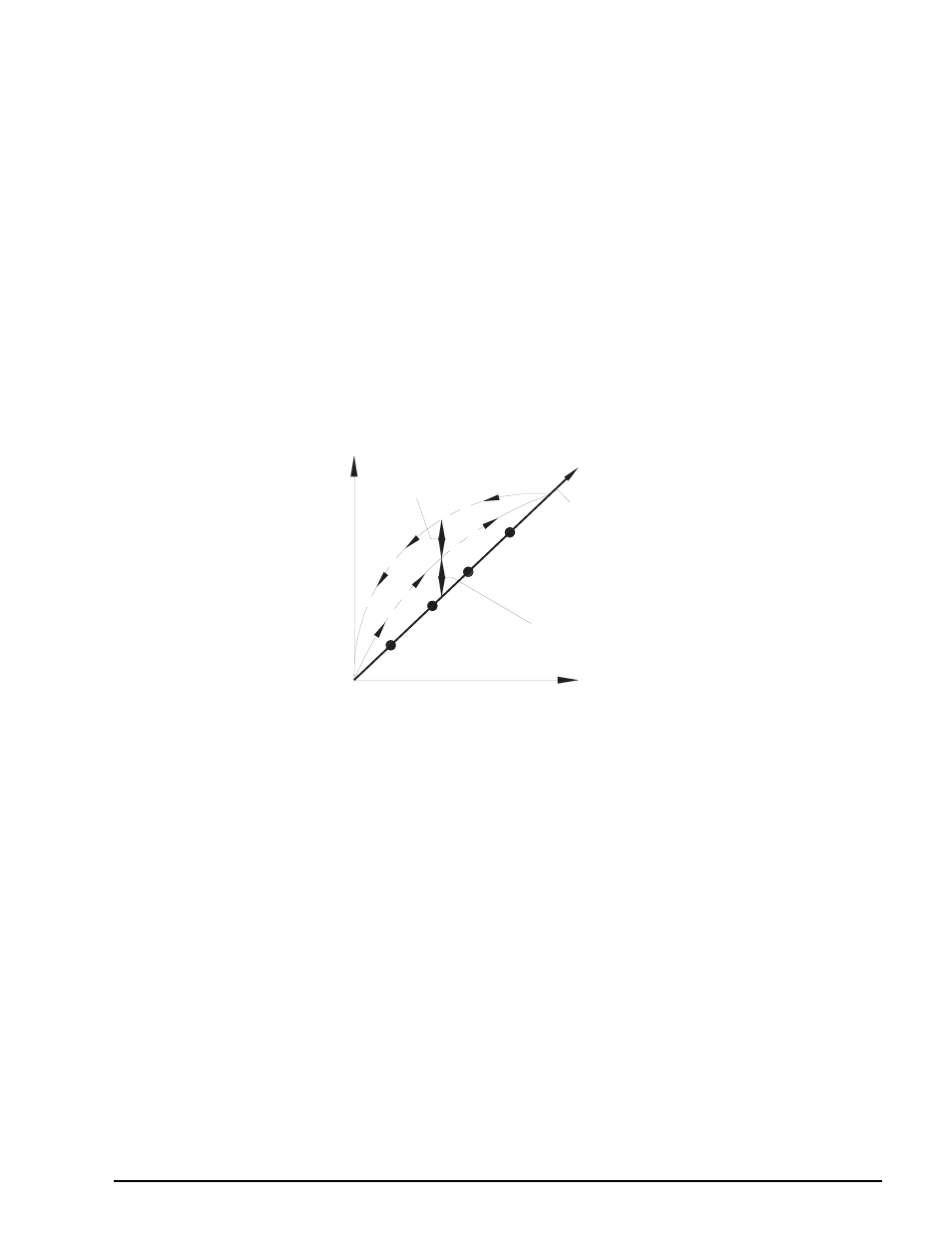
Span Calibration Points
There are a total of 10 calibration points (SPAN 1 - 10 CAL TARGET) which are sequentially entered. It is not
required that all calibration points be entered. If calibration is performed with less than 10 points, the curve is
extrapolated to full capacity based upon the slope correction between the last two entered SPAN CAL points. In
the example below, if only four span calibration points were entered (SPAN 1 to SPAN 4), the slope correction
from SPAN 4 to full capacity would be defined by the computed slope between SPAN 3 and SPAN 4.
NOTE: If fewer than 10 SPAN CAL points are desired during calibration, simply step past the remaining calibration
points using the DOWN arrow key, until the HYSTERESIS calibration point is reached.
Figure 5-5. Span Calibration Points
5.9
Resetting Span Calibration Points
To reset the span calibration points, use the
DOWN
arrow key to step to the desired SPAN CAL point and then
press the
CE
key. The correction factor of the selected SPAN CAL point and all others beyond will be reset to
unity (see Section 5.6 on page 16).
NOTE: X’s shown on LED display and alpha-numeric display columns represent existing data.
After a reset has been performed, entry of new SPAN CAL points proceeds as described in Section 5.6.1 on
page 17, starting with step 3.
NOTE: If all 10 SPAN CAL points are not used in the calibration, the last span calibration point to appear (SPAN x CAL
TARGET=xx.xx) is not an entered correction point. It only indicates the next span calibration that can be entered.
5.10 Overwriting Span Calibration Points and Hysteresis
Any SPAN CAL point can be overwritten with a new value provided that it remains within the range bounded by
the span calibration points above and below the span point to be overwritten. Figure 5-6 on page 20 shows SPAN
2 CAL point being redefined within the boundaries set by SPAN 1 and SPAN 3. HYSTERESIS can also be
overwritten as long as the new entry is below 80% of the full capacity value. For information on how to reach
SPAN CAL point and HYSTERESIS, see Section 5.6 on page 16.
0
LOAD
mV/V OUTPUT
HYSTERESIS\PERROR
NON-LINEARITY\PERROR
DESIRED LINEARITY FROM ZERO TO RATED OUTPUT
SPAN 4
SPAN 3
SPAN 2
SPAN 1