Condec DLR3110 User Manual
Page 6
2
DLR3110 Rack Mount Digital Pressure Calibrator Manual
By combining these sensors with microprocessor-based circuitry, an even higher degree of operational accuracy
and precision has been accomplished. For example, computer-generated correction curves for both the
non-linearity and the hysteresis of the sensors improve these characteristics by an order of magnitude or more.
Two micro-metering valves and vernier are provided to control the external nitrogen source while the digital
display indicates the magnitude of the applied test pressure. Also, a push-button switch provides the “zeroing” of
the pressure display (on GAGE models). Over-pressure protection, based on model, is provided via a fully
adjustable pressure regulator which is manually set for each new device being tested.
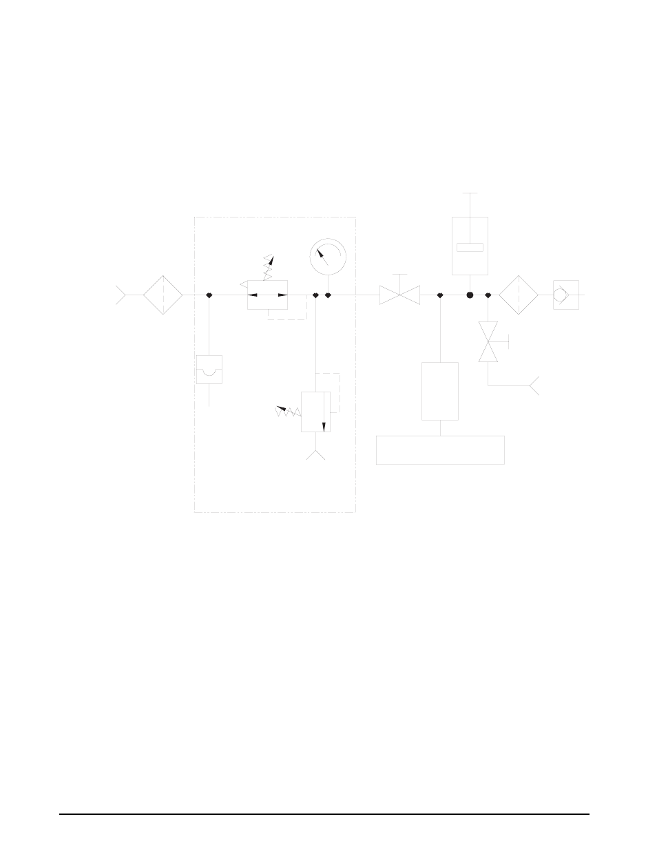
Figure 1-1 provides an overview of the DLR3110’s function.
Figure 1-1. DLR3110 Flow Diagram
MONITOR
PRESSURE LIMIT
RELIEF
VALVE
INPUT PORT
±50 PSI
3000 PSI
BURST DISK
CONTROL
PRESSURE LIMIT
FILTER
20u
MICROPROCESSOR-BASED
DIGITAL INDICATOR
TRANSDUCER
VENT
VENT/VACUUM
PORT
(QUICK DISCONNECT)
PRESSURE
INCREASE
VERNIER
TEST PORT
20u
FILTER
ADJUST
DLR3110 FLOW DIAGRAM
NOT REQUIRED ON 5K OR 10K MODELS
NOTE: MAX INPUT BASED\P ON MODEL.