Condec UPS3210 User Manual
Operation & maintenance manual
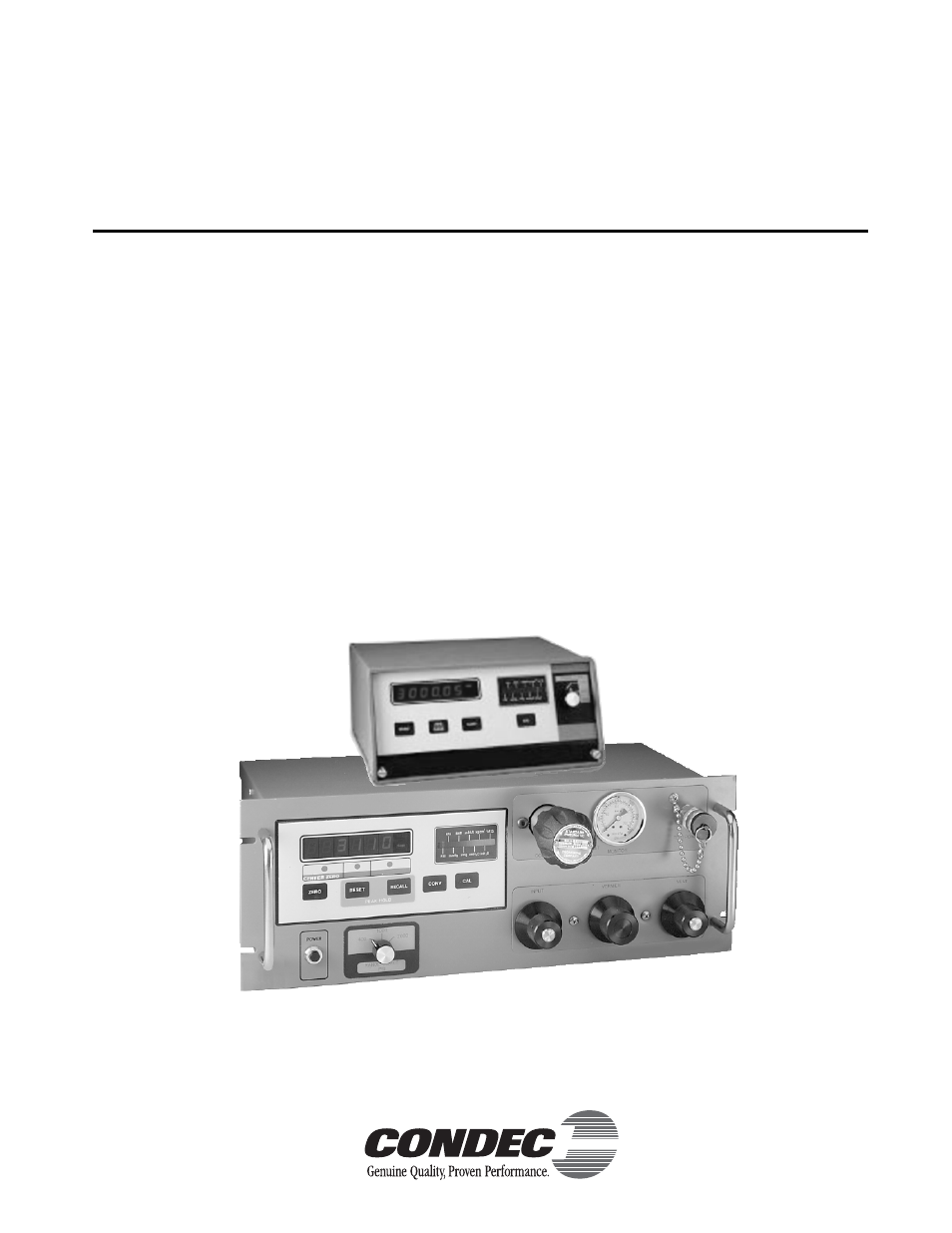
Table of contents
Document Outline
- About This Manual
- 1.0 Introduction
- 2.0 Operation
- 2.1 Unpacking and Inspection
- 2.2 Standard Display/Keyboard Front Panel Functions
- 2.3 Rear Panel Configuration
- 2.4 Configuration Switch Settings
- 2.4.1 APC4000/APC4001 Interface Option Enable
- 2.4.2 Peak Hold or MAX/MIN Option Enable
- 2.4.3 Conversion Enable
- 2.4.4 Digital Averaging
- 2.4.5 AUTO-ZERO Maintenance (AZM) Enable
- 2.4.6 Automatic Span Maintenance (ASM) Enable
- 2.5 Freeze Mode Option Wiring
- 2.6 Engineering Conversion with PEAK HOLD or MAX/MIN Option
- 2.7 UPS3000 or UPS3210 Initial Setup Sequence
- 2.7.1 UPS3000 or UPS3210 Display of Pressure Sequence GAGE Mode
- 2.7.2 UPS3000 or UPS3210 Display of Pressure Sequence Absolute (ABS) Mode
- 2.8 UPS3110 Initial Setup Sequence
- 2.8.1 UPS3110 Pressure Measurement Sequence GAGE Mode
- 2.8.2 UPS3110 Pressure Measurement Sequence Absolute (ABS) Mode
- 2.9 GAGE Mode Self-Check
- 2.10 Battery Operation
- 2.11 Serial Output: 20 mA Loop
- 2.11.1 Hardware Configuration
- 2.11.2 Serial Output Software Configuration
- 2.11.3 DATA FORMAT TABLE
- 2.11.4 SERIAL OUTPUT CONFIGURATION TABLE
- 3.0 Calibration and Adjustment Procedure
- 3.1 Pneumatic Calibration Set-Up
- 3.2 Instrument Calibration Set-Up
- 3.3 Zero/Span Calibration
- 3.4 Linearity and Hysteresis Calibration
- 3.5 Shunt Resistor Calibration
- 3.6 Permanent Data Storage
- 3.7 Barometric Offset - Absolute/Gage Switch Selectable Units ONLY
- 3.7.1 For UPS3000/UPS3210 Absolute/Gage Switch Selectable Units ONLY
- 3.7.2 For UPS3110 Absolute/Gage Switch Selectable Units ONLY
- 4.0 Maintenance & Service
- 4.1 Troubleshooting
- 4.2 Maintenance & Service Procedures
- 4.2.1 Case Removal and Installation
- 4.2.2 ORION 2C (PN 55283) or ORION 3A (PN 55287) Manifold Removal
- 4.2.3 ORION Manifold - Valve Seat Removal
- 4.2.4 ORION Manifold - Vernier Control Disassembly
- 4.2.5 ORION Manifold - Vernier Control Reassembly
- 4.2.6 ORION Manifold - Valve Seat Installation
- 4.2.7 ORION - Manifold, Panel Installation
- 4.2.8 ORION 2C Manifold - Valve Adjustment Procedure
- 4.2.9 ORION 3A Manifold - Valve Adjustment Procedure
- 4.2.10 Pressure Limit Control (Standard Pneumatic), Regulator Removal
- 4.2.11 Pressure Limit Control (Standard Pneumatic), Regulator Installation
- 4.2.12 Pressure Limit Control (Tescom), Regulator Removal
- 4.2.13 Pressure Limit Control (Tescom), Regulator Installation
- 4.2.14 Panel Gauge Removal
- 4.2.15 Panel Gauge Installation
- 4.2.16 Test Port Quick-Connect Fitting (PN 59762) Removal and Installation - 15, 50 and 100 Full Scale PSI
- 4.2.17 Test Port Quick-Connect Fitting (PN 55426), Removal and Installation - 500, 1000 and 2000 Full Scale PSI
- 4.2.18 Test Port Filter (PN 54188), Removal and Installation - 500, 1000 and 2000 Full Scale PSI
- 4.2.19 Test Port Filter (PN 54188), Removal and Installation - 15, 50 and 100 Full Scale PSI
- 4.2.20 Test Port Quick-Connect Fitting (PN 59004) and Filter (PN 54188) Removal and Installation - 5000 and 10000 Full Scale PSI
- 4.2.21 AC Fuse (PN 58076), Removal and Installation
- 4.2.22 AC Power/EMI Line Filter (PN 58870), Removal and Installation
- 4.2.23 Power Switch Cable (PN 55351), Removal and Installation (Battery Units)
- 4.2.24 Power Switch (PN 58878), Removal and Installation
- 4.2.25 Range Select Switch Cable (PN 56014), Removal and Installation
- 4.2.26 Power Supply Assembly, Removal and Installation (Battery Units)
- 4.2.27 BATTERY (55851), Removal, Installation and Adjustments
- 4.3 ORION 2C Valve Assembly Parts List
- 4.4 ORION 3A Valve Assembly Parts List
- 4.5 UPS3000 Assembly Drawings
- 5.0 Model Number System
- 6.0 Available Ranges, Multi-Conversions and Resolutions
- 7.0 Options, Replacement Kits
- 8.0 Specifications
- UPS3000/UPS3110/UPS3210 Warranty and Return Policy
- UPS3000/UPS3110/UPS3210 Return Material Authorization Form