0 installation and wiring, 1 unpacking and inspection, 2 repacking – Condec DLR3110 User Manual
Page 7: 3 rear panel configuration, Installation and wiring
Installation and Wiring
3
2.0
Installation and Wiring
2.1
Unpacking and Inspection
Carefully remove the instrument from its shipping container. A visual inspection of the instrument's external
surfaces should be performed immediately after unpacking. If obvious damage occurred during transit, notify the
shipping agency and distributor as soon as possible to receive instructions on how to proceed after an assessment
of the damage is completed.
If the instrument shows no signs of damage, check to be sure all the required equipment and accessories were
included. Keep original shipping carton for repacking in case repair is necessary.
2.2
Repacking
If the DLR3110 must be returned for repair, recalibration, or modification, be sure that it is properly cushioned
and packed and that a description of the work to be performed is included. The original shipping carton should be
kept for this purpose.
2.3
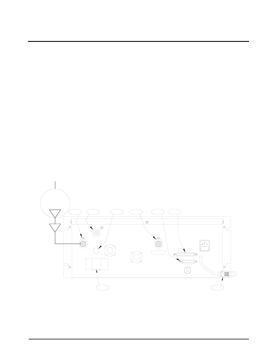
Rear Panel Configuration
The rear panel of the rack mount DLR3110 Series, contains the following items:
•
AC power cord (1) and input receptacle.
•
7/16-20, 37
°
-4 AN male fittings, vent/vacuum port (2) and input pressure port (3).
NOTE: The maximum input pressure, supplied by user, is noted below input pressure port.
•
The unit's identification plate (4) and J6, 25 pin D connector, (5) for serial I/O communication interface.
•
Optional if required items: Connector J5, 37 pin D connector, (6) for the Parallel BCD output. Connector
J2 (7) for the Freeze mode cable. Test port (8) in place of front mounted.
Figure 2-1. DLR3110 Rear View
PUMP
VACUUM
INPUT
MAX. XXX
REAR VIEW
4
PORT
VENT/VACUUM
J2
FREEZE MODE
J3
J1
3
1
FUSE
AC INPUT
TEST PORT
J6
J5
2
5
6
7
8