2 printer (port one or port two), 3 duplex (port one only) – Condec DLR3110 User Manual
Page 37
Serial Input/Output
33
6.2
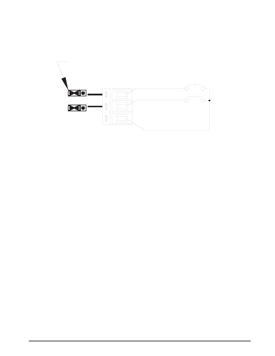
Printer (Port One or Port Two)
The selection of the PRINTER format is an on-demand serial data transmission that is initiated each time the
front panel
key is pressed or when a remote print input is issued. This mode of serial data output is used
when interfacing to printers.
Figure 6-1. Printer Port One and/or Port Two Wiring
The data output format of the serial transmission is of the general form shown below:
Where:
<,>
=
Brackets are not sent in the transmission of the output data string.
Pol
= Single character field that defines polarity of data. Positive data would be space character
(20H) and negative data will have a “-” character (2DH).
Data
= Seven (7) digit numeric data field that includes decimal point and/or fixed dummy zero when
applicable. Leading zeroes are suppressed and an ASCII space character (20H) is
transmitted to hold the position of each leading zero.
space
=
Space character (20H)
Units
=
A character field that defines the current units of the display data (examples: PSI, cmH2O,
Kpa, mBAR, BAR, PASCAL).
Mode
=
An alpha character field that describes the current mode the indicator is in. GAGE/
ABSOLUTE/Delta P
CR
=
Carriage return
LF
=
Line feed
6.3
Duplex (Port One Only)
The selection of the DUPLEX format is only available on Port One. This selection sets up port 1 for bidirectional
communication in RS485, RS232, or 20mA. Because of the extensive list of command instructions that can be
issued to the indicator from a host computer, the scope of this section is limited to defining those commands that
are most often utilized. A more extensive document detailing the full operational parameters for serial duplex
protocol is available upon request from CONDEC. Ask for Duplex Serial Protocol Manual, PN 74845.
•
The duplex protocol includes the following basic functions:
d) Setup entry and recall
e) Current weight/pressure data recall
f) Calibration and correction recall and entry
g) All front panel key functions
h) Temperature calibration and correction recall and entry
TB2
S4
OUT
S5
IN
RETURN
I/O 1
I/O 2
(DIGITAL COMMON)
JUMPER PLUGS SHOWN ON S4 & S5 CONFIGURED AS AN INPUT