Input 1 wiring, Thermocouple, Rtd (2- or 3-wire) 100platinum – Watlow Series 97 User Manual
Page 16: Input 2 wiring, Digital event, Input 1, Input 2, Figure 3.6a, Figure 3.6b, Figure 3.6c
3 . 6
■
W i r i n g
Wa t l o w S e r i e s 9 7
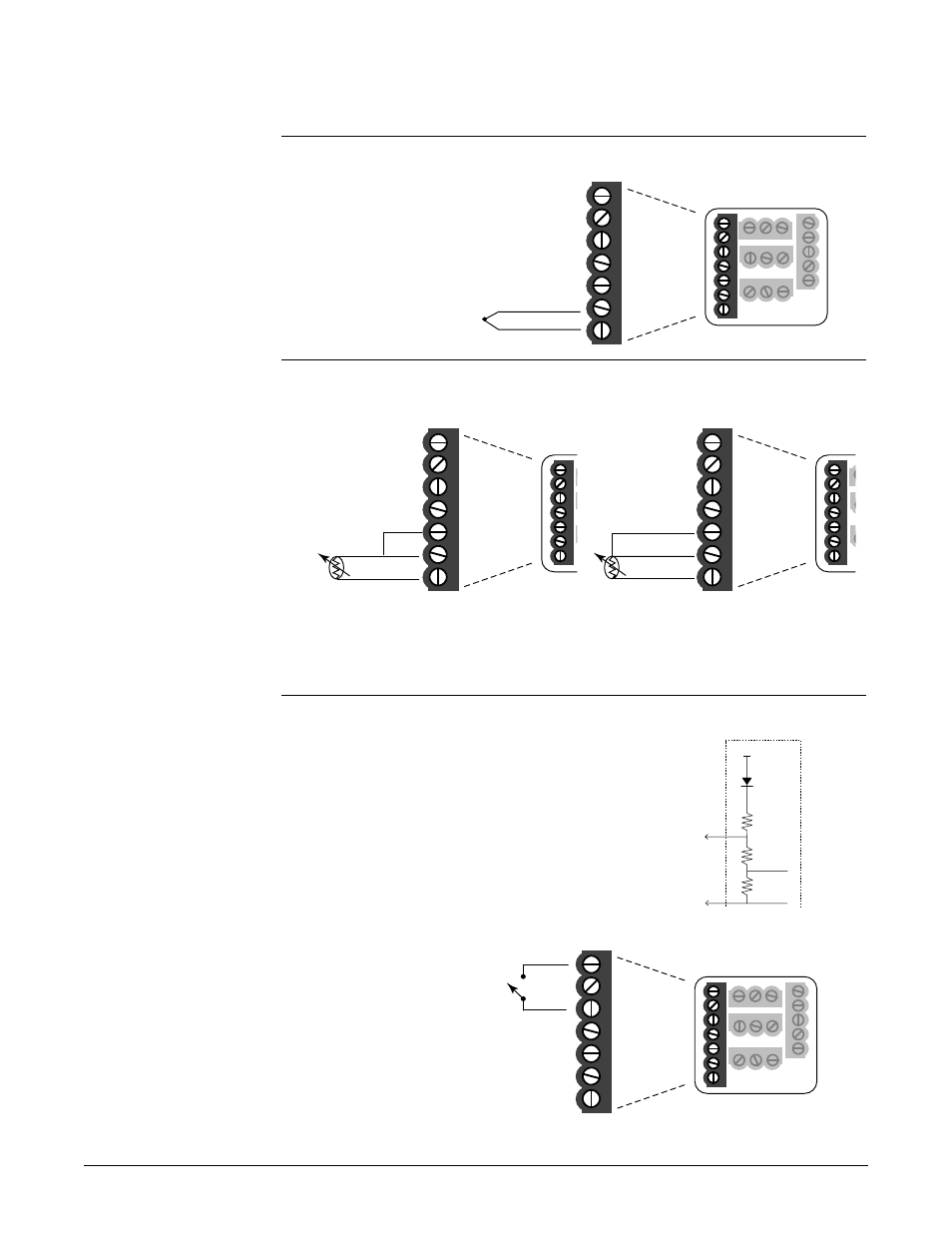
Input 1 Wiring
Figure 3.6a
– Thermocouple
Available on all units
Impedance: 20M
Ω
Figure 3.6b
– RTD (2- or 3-Wire) 100
Ω
Platinum
Available on all units
Input 2 Wiring
Figure 3.6c –
Digital Event
97 _ 1 - _ _ _ _ - _ _ _ _
Voltage input
3-36VÎ (dc) Event Input High State
0-2VÎ (dc) Event Input Low State
Contact closure
0-2k
Ω
Event Input Low State
> 23k
Ω
Event Input High State
10
8
1
2
3
4
5
6
7
13 14 15
11
12
16 17 18
19 20 21
9
3
1
+
-
2.67k
Ω
EVENT
+
3
EVENT
-
1
20k
Ω
100
Ω
+5V
1
2
3
4
5
6
7
1
5
6
7
S1
S2
S3
3-wire
1
2
3
4
5
6
7
6
7
S1
S3
5
2-wire
jumper 5 to 6
10
8
1
2
3
4
5
6
7
13 14 15
11
12
16 17 18
19 20 21
9
- 6
+7
NOTE:
Successful installation
requires five steps:
• Choose the controller’s
hardware configuration
and model number
(Appendix);
• Choose a sensor
(Chapters 3 and 6, and
Appendix);
• Install the controller
(Chapter 2);
• Wire the controller
(Chapter 3) and
• Configure the controller
(Chapters 4, 5 and 6).
ç
WARNING:
To avoid damage to
property and equipment,
and/or injury of loss of
life, use National Electric
Code (NEC) standard
wiring practices to
install and operate the
Series 97. Failure to do
so could result in such
damage, and/or injury or
death.
ç
CAUTION:
Maintain isolation
between input 1 and
input 2 to prevent a
ground loop. A ground
loop may cause incorrect
readings, dashes across
the upper display or the
display of error codes.
Failure to follow this
guideline could result in
damage to equipment
and product.