Power wiring, Sensor installation guidelines – Watlow Series 97 User Manual
Page 13
Wa t l o w S e r i e s 9 7
W i r i n g
■
3 . 3
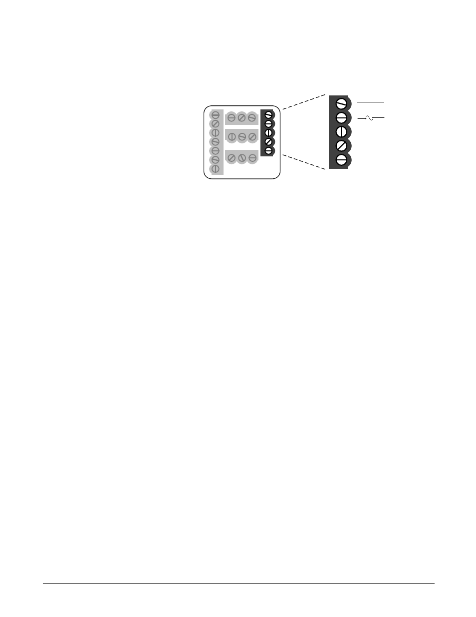
Power Wiring
100 to 240VÅ (ac), nominal (85 to 264 actual) 97 A _ - _ _ _ _ - _ _ _ _
24 to 28V‡ (ac/dc), nominal (21 to 30 actual) 97 B _ - _ _ _ _ - _ _ _ _
Figure 3.3 - Power wiring.
Sensor Installation Guidelines
Thermocouple inputs: Extension wire for thermocouples must
be of the same alloy as the thermocouple to limit errors.
When using a voltage input for the digital event on Input 2, use
an ungrounded thermocouple on Input 1. If a grounded
thermocouple is required, the signal to input 2 must be isolated
to prevent possible ground loops.
RTD input: Each 1
Ω
of lead wire resistance can cause a +2°F
error when using a two-wire RTD. A three-wire RTD sensor
overcomes this problem. All three wires must have the same
electrical resistance (i.e., same gauge, same length, multi-
stranded or solid, same metal).
10
8
1
2
3
4
5
6
7
13 14 15
11
12
16 17 18
19 20 21
Fuse
L2
L1
-
9
8
9
+
ç
CAUTION:
If high voltage is applied
to a low-voltage unit,
irreversible damage will
occur.
ç∫
WARNING:
To avoid damage to
property and equipment,
and/or injury of loss of
life, use National Electric
Code (NEC) standard
wiring practices to install
and operate the Series
97. Failure to do so could
result in such damage,
and/or injury or death.
ç
CAUTION:
Maintain isolation
between input 1 and
input 2 to prevent a
ground loop. A ground
loop may cause incorrect
readings, dashes across
the upper display or the
display of error codes.
Failure to follow this
guideline could result in
damage to equipment.