Chapter two installation, Chapter 2: installation – Watlow Power Series Rev H User Manual
Page 7
Chapter Two
Installation
Installation, Chapter 2
Watlow Power Series
I
2.1
2
The following two chapters will explain how to install the Power Series
controller. Watlow power controllers are thoroughly tested before leaving the
factory, so the Power Series controller is ready to install when you receive it.
Chapters 2 and 3 describe the steps required to install the Power Series
controller. Refer to Chapter 2 for mounting information and Chapter 3 for input,
power, and load wiring of the Power Series.
Before beginning installation, read through these chapters to gain an under-
standing of the entire installation. Consider the installation carefully. Plan the
power, load, and input signal wiring before mounting the Power Series. Also
consider the cabinet space, controller dimensions, wire bending radius, and air-
flow. Use good wiring practices to minimize electrical noise problems.
∫
WARNING:
To avoid potential electric
shock and other hazards,
all mounting and wiring
for the Power Series must
conform to the National
Electric Code (NEC) and
other locally applicable
codes.
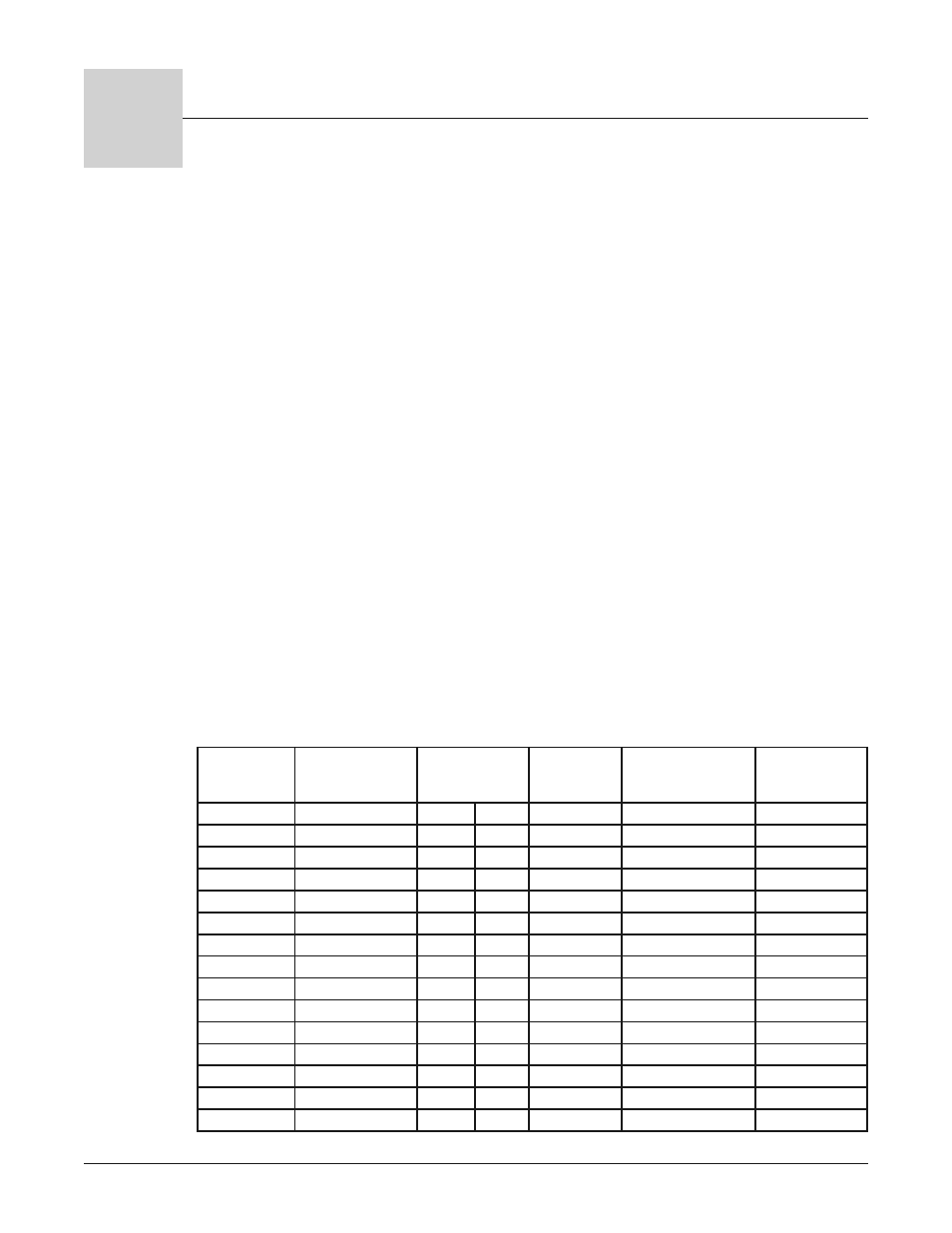
Power Series Wire Bending Radius at Base Current and Ambient
Temperature Rating and Replacement Semiconductor Fuses
Minimum recommended wire sizes are based on the NEC 30°C ambient with not
more than three current carrying conductors in raceway or cable, while also
considering the Power Series 50°C enclosure temperature and semiconductor
fuse rating. Use copper conductors only.
The terminal lug wire range for all Power Series amperages is 350 MCM to 6
AWG. The recommended terminal torque is 180 in.-lbs. (20 Nm.). Refer to page
3.1 for torque guidelines.
NOTE: Ground must be
wired with the same size
wire as line and load
connections to a ground
of sufficient current
carrying capacity.
NOTE: Integral semicon-
ductor fuses do not
qualify as branch circuit
protection.
Power Series
Current (Amps)
Minimum
Recommended Wire
Size (90C) (AWG)
Wire Bending
Radius
mm inches
Semiconductor
Fuse Rating
(Amps)
Watlow Replacement
fuse P/N
Bussmann
Replacement Fuse
P/N
65
6 AWG
51
2.0
100
0808-0102-0100
170M1317
80
4
76
3.0
125
0808-0102-0125
170M1318
85
4
76
3.0
125
0808-0102-0125
170M1318
90
4
76
3.0
125
0808-0102-0125
170M1318
100
3
76
3.0
160
0808-0102-0160
170M1319
105
3
76
3.0
160
0808-0102-0160
170M1319
120
2
89
3.5
160
0808-0102-0160
170M1319
125
2
89
3.5
160
0808-0102-0160
170M1319
140
1
114
4.5
200
0808-0102-0200
170M1320
155
1/0
140
5.5
200
0808-0102-0200
170M1320
160
1/0
140
5.5
250
0808-0102-0250
170M1321
165
1/0
140
5.5
250
0808-0102-0250
170M1321
185
2/0
152
6.0
250
0808-0102-0250
170M1321
200
3/0
165
6.5
250
0808-0102-0250
170M1321
250
250 MCM
216
8.5
315
0808-0102-0315
170M1322