Checking and replacing fuses, Checking and replacing fuses . . . . .a.6, Checking and replacing fuses . . . . . . .a.6 – Watlow Power Series Rev H User Manual
Page 60
A.6
I
Watlow Power Series
Appendix
Analog to digital failure error.
Condition For Alarm or Error To Occur
Alarm / Error
[`err]
System Errors
Heater Bakeout Overcurrent = 0x0001
SCR Short = 0x0002
System Configuration = 0x0004
AD Reference Fail = 0x0008
Checksum Error = 0x0010
Ram Error = 0x0020
Over Temperature Error = 0x0040
Half Cycle Loss = 0x0080
Phase Rotation = 0x0100
Any system-level errors that are active will be repre-
sented in binary. As an example, if the power source
is losing half cycles and an over temperature condi-
tion exists, Modbus register 195 will contain 0x00C0.
Over temperature Error = 0000000001000000
Half Cycle Loss = 0000000010000000
[`err]
Heater Bakeout
[HbOC]
Overcurrent Error
Error will occur when the maximum heater current during heater bakeout has been
exceeded.
[`err]
Shorted SCR Error
[shrt]
The shorted SCR error is detected by measuring current when the SCR is de-energized
and comparing this reading to the current measured when the SCR is energized. A shorted
SCR error is activated if the de-energized current reading is at least 10A and 25% or more
of the energized current reading.
[`err]
System Configur-
[shrt]
ation Error
Invalid hardware configuration error.
[`err] Analog to Digital
[``Ad]
Failure Error
Incorrect phasing. Error will occur on a three-phase system with a [3L`d] load or on a
multizone (PC8 and PC9) operating on a three-phase power supply under phase angle con-
trol if the phasing is incorrect. Must be A,B,C phase rotation (CW).
[`err] Half Cycle Line
[HCyl]
Loss Error
Error will occur if a load half cycle loss is detected during five consecutive zone restart
attempts.
[`err] Phase Rotation
[p|`rOt]
Error
[`err] Over Temperature
[``Ot]
Error
Error will occur when heat sink temperature is greater than factory shutdown temperature
[`sdÇ].
[`err] Ram Error
[ram]
Error will occur when RAM failure is detected.
[`err] Checksum Error
[`Che]
Invalid checksum in non-volatile memory error.
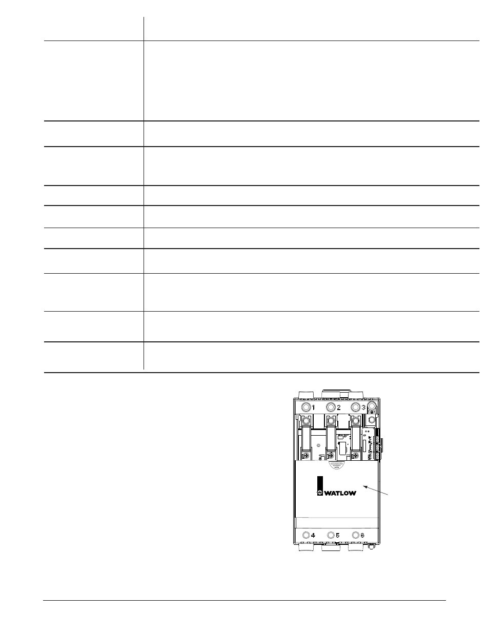
Checking and Replacing Fuses
Ensure that all high voltage power is off. Slide the fuse cover
down. Using an ohmmeter, measure the dc resistance of the fuse to
determine if it is open. (Typical dc resistance is less than 1 ohm.)
If fuse is open, replace it by removing the old fuse using a 1/2 inch
socket and a #3 Phillips screwdriver. Be careful not to drop washers off
the bolt or screw ends. If they have dropped into the case, shake them
out gently.
The bolt will have 2 washers. The bottom machine screw will have
2 or 3 washers, depending on the size of the SCR in the unit. It is
important that the washers are replaced in the exact order
in which they were removed. Take care installing the fuse so
that its orientation matches the image that is printed on the PC
board.
With the new Cooper Bussman fuse in the unit, torque the bolt to 44
inch-pounds and the screw as follows: For models PXX-F20X-XXXX
and PXX-N20X-XXXX torque to 26 in.-lbs. (2.93 Nm.). For models
PXX-F25X-XXXX, PXX-N25X-XXXX, PXX-F30X-XXXX, PXX-F35X-
XXXX, and PXX-N30X-XXXX, torque to 44 in.-lbs. (4.95 Nm.). Close
fuse cover. If unit was taken off the wall, observe all terminal torque
specs when reconnecting wires. Unit should now be ready to resume
operation. Reapply power to the controller and line/load terminals.
Fuse
Fuse
Fuse
Fuse
Cover
Power Series
Solid State Power Control
Figure A.6 — Fuse location.
Note: The fuse must be a Cooper Bussman to
retain SCCR rating.