Chapter three wiring, Chapter 3: wiring, Torque guidelines – Watlow Power Series Rev H User Manual
Page 13: Wiring the power series controller
Chapter Three
Wiring
Wiring the Power Series Controller
Wiring options depend on the model number. Check the terminal designation stickers on the
right side of the controller and compare your model number to those shown here and with
the model number breakdown in the Appendix (page A.10) of this manual.
Chapter 3 illustrates how to wire the inputs and outputs for all options. Refer to Figure 3.1
for terminal torque guidelines.
Torque Guidelines
•
Properly torque terminals by holding for 30 seconds to allow for wires to settle and
minimize loosening due to cold flow.
•
Re-torque all terminals after 48 hours.
•
Establish a maintenance program to re-torque line and load terminations every 3-6
months.
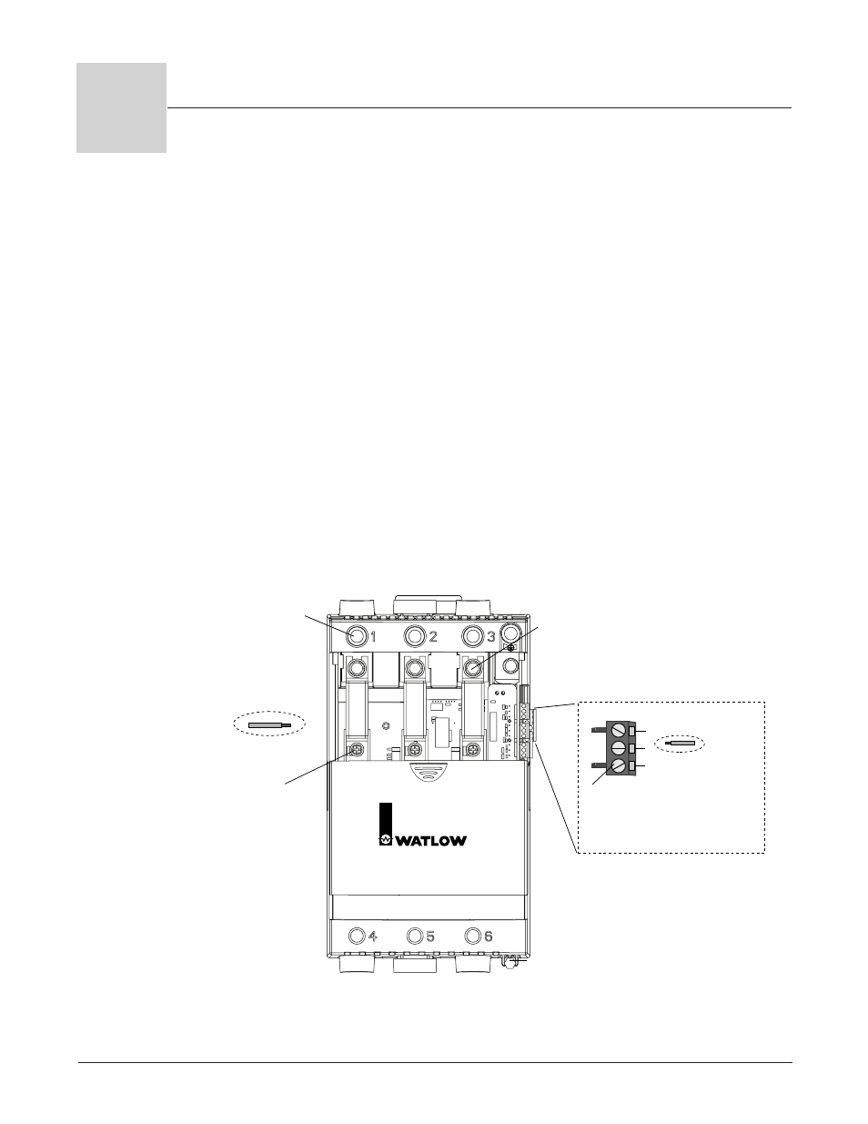
Figure 3.1 — Torque and wire stripping.
Terminals 1 - 6
and Ground Lug
Torque to
180 in.-lbs.
(20 Nm.)
with 3/8 inch
Allen wrench
provided.
Strip wires
1-1/8 inch (30mm)
#3 Phillips
Screws for Fuse
Mounting
For models
PXX-F20X-XXXX
PXX-N20X-XXXX
Torque to
26 in.-lbs. (2.93 Nm.)
For models
PXX-F25X-XXXX
PXX-N25X-XXXX
PXX-F30X-XXXX
PXX-N30X-XXXX
PXX-F35X-XXXX
Torque to
44 in.-lbs. (4.95 Nm.)
5/16 inch Bolts
for Fuse Mounting
Torque to 44 in.-lbs.
(4.95 Nm.)
Strip wires
0.24 in. (6mm)
Torque to 8 in.-lbs. (0.9 Nm.) using
a 1/8 inch (2.5 mm) blade screwdriver.
Accepts 12-22 AWG or 2 No. 22-18
AWG wires.
Controller Connectors
Allen Wrench
(Flat surface must be against the case.)
Fuse
Fuse
Fuse
Power Series
Solid State Power Control
3
W i r i n g , C h a p t e r 3
Wa t l o w P o w e r S e r i e s
I
3 . 1