Power/output wiring, Line power/output wiring, Single phase output wiring – Watlow Power Series Rev H User Manual
Page 16: 3 phase, 2-leg, 4 scr output wiring, Figure 3.4a
3 . 4
■
Wa t l o w P o w e r S e r i e s
W i r i n g , C h a p t e r 3
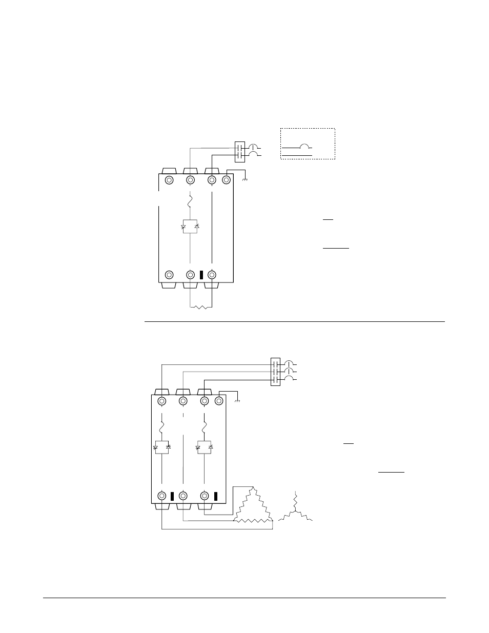
Line Power/Output Wiring
Figure 3.4a –
Single Phase Output Wiring
(Model PC1X-XXXX-XXXX)
Figure 3.4b –
3 Phase, 2-Leg, 4 SCR Output Wiring
(Model PC2X-XXXX-XXXX)
NOTE: Our illustrations illustrate circuit breakers for branch circuit protection. Fuses can
also be used.
L2
L1
L3
4
5
6
Limit Control
Contacts
(If Required)
Internal Bussbar
Heater
2
Gnd
1
3
4
5
6
On-board
Semiconductor
Fuses
ref.1
ref.3
L1
L2
Limit Control Contacts
(If Required)
240V~
and above
Internal Bussbar
2
Gnd
1
3
4
5
6
Heater
On-board
Semiconductor
Fuse
120V~
and 277V~
L1
Neutral
ref.2
NOTE:
Successful installation
requires four steps:
• Choose the controller’s
hardware configuration
and model number
(Appendix);
• Install the controller
• Wire the controller
• Configure the controller
ç∫
WARNING:
To avoid damage to
property and equipment,
and/or injury or loss of
life, use National Electric
Code (NEC) standard
wiring practices to install
and operate the Power
Series. Failure to do so
could result in damage,
and/or injury or death.
NOTE:
Torque and wire strip
guidelines:
• Connections 1 thru 6,
and ground lug
• Strip wire 1-1/8 in.
(30mm). Torque to 180
in.-lbs. (20 Nm).
• Hold torque for 30
seconds to allow for
wiring settling and cold
flow. Re-torque after
48 hours.
• All load connections
should be re-torqued
every 3-6 months.
ç
CAUTION: Figure 3.4a shows the
Watlow-recommended output wiring
using the internal bussbar as a
return current path and with ref. 2
not connected. Should a user choose
a non-recommended wiring scheme,
then ref. 2 or the internal bussbar
must be connected to the
appropriate line or neutral. Failure
to follow these guidelines could
cause damage to the Power Series.
ç
CAUTION: Figure 3.4b shows the
Watlow-recommended output wiring
using the internal bussbar as a
return current path and with ref. 1
and 3 not connected. Should a user
choose a non-recommended wiring
scheme, then ref. 1 or ref. 3 or the
internal bussbar must be connected
to the appropriate line. Failure to
follow these guidelines could cause
damage to the Power Series.