Step 5, Serial bus system, Placing serial bus modules – Ross Controls ROSS MODULAR I User Manual
Page 49
49
www.rosscontrols.com
Power Supply Distance Rating
Modules are placed to the right of the power supply. Each
Serial Bus module can be placed in any of the slots to
the right of the power supply until the usable backplane
current of that supply has been exhausted. An adapter
provides 1 A current to the PointBus. The RPSSSE24A
provides up to 1.3 A and I/O modules require from 75 mA
(typical for the digital and analog I/O modules) up to 90
mA or more.
PointBus Current Requirements
Part Number
PointBus Current
Requirements
RPSSN8xxx
75 mA
RPSSP8xxx
RPSST8xxx
RPSSTR4MRA
90 mA
RPSSNACM12A
75 mA
RPSSTACM12A
RPSSNAVM12A
RPSSTAVM12A
RPSSV32A
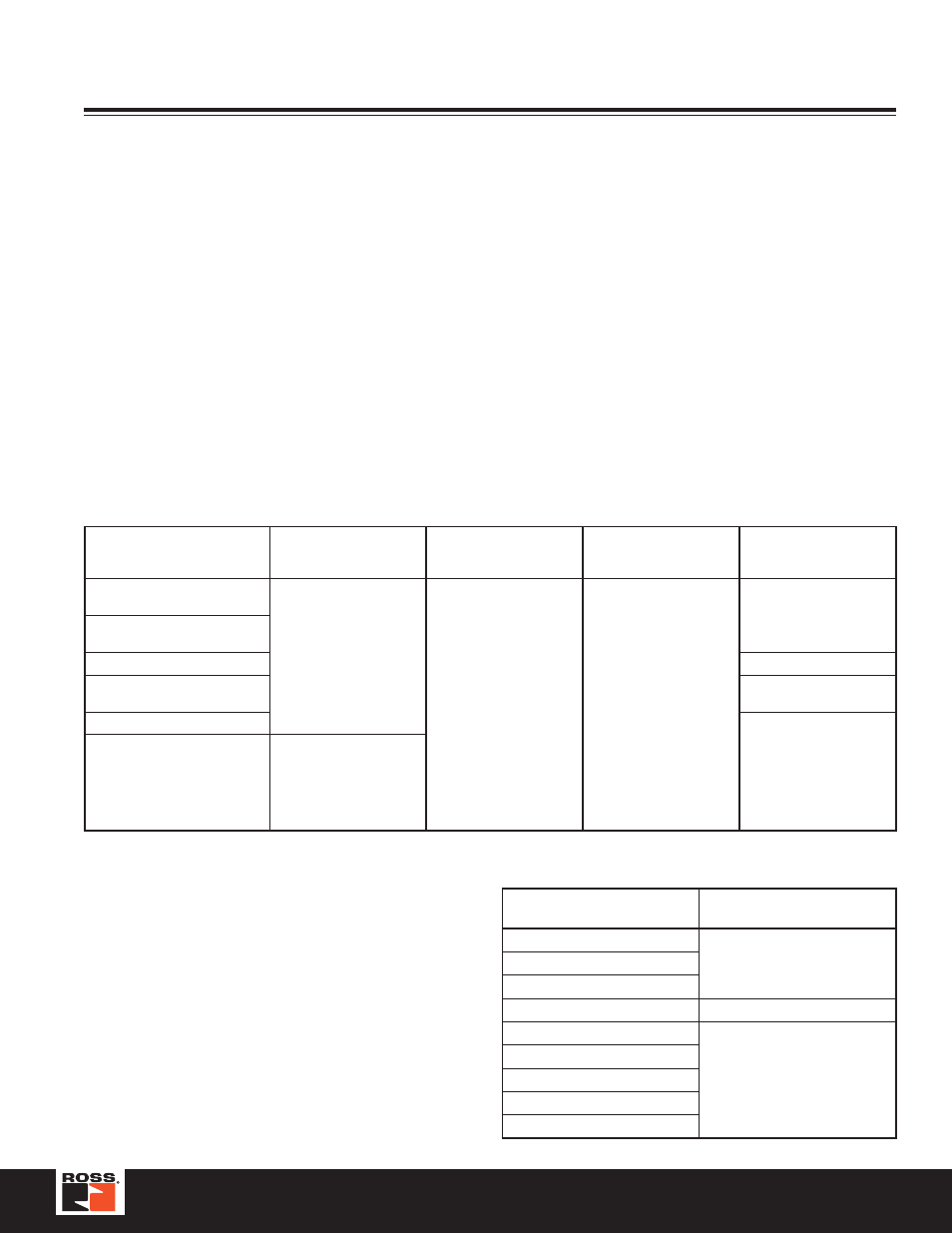
Maximum Size Layout
Part Number
PointBus Current (mA)
Maximum I/O Modules
with 24VDC Backplane
Current at 75 mA each
Maximum I/O Modules
with Expansion Power
Supplies
Maximum Number of I/O
Module Connections
RPSSCDM12A on
DeviceNet™
1000
Up to 13
63
RPSSCDM18PA on
DeviceNet™
RPSSCCNA on ControlNet™
5 rack and 20 direct
RPSSCENA on EtherNet/IP™
20 total connections
including rack and direct
RPSSCPBA on PROFIBUS
Not to exceed scanner
capacity
RPSSSE24A Expansion Power
Horizontal mounting:
1A@5VDC for 10...19.2V
input; 1.3A @ 5VDC for
19.2...28.8V input Vertical
mounting: 1A @ 5VDC for
10...28.8V input
Step 5
Placing Serial Bus Modules
Determining Mounting Requirements
The producer / consumer model multicasts messages.
This means that multiple nodes can consume the
same data at the same time from a single device.
Where you place I/O modules in the control system
determines how the modules exchange data.
For a Rockwell controller to control Serial Bus, the I/O
must be:
• On the same network as the controller
or
• On a ControlNet™ network that is local to that
controller or
• On an EtherNet/IP™ network that is local to that
controller
Serial Bus System