Manifolds - series w66 size 00 & 0 (15407-2), Manifolds — series w66, Maximum solenoids energized simultaneously – Ross Controls ROSS MODULAR I User Manual
Page 19: Example
19
www.rosscontrols.com
Maximum Solenoids Energized
Simultaneously
(Interconnect Circuit Boards)
Size 00 & 0 (15407-2)
1. List Manifold Assembly call out. This automatically includes the
end plate kit assembly.
2. List complete Valve, Regulator, Flow Control and Base model
number. List left to right, LOOKING AT THE CYLINDER PORTS
on the #12 end of the manifold.
The left most station is station 1. (If a blank station is needed,
list the blanking plate part number and the individual manifold
number in the station specified.)
18mm
Station 1
18mm
Station 2
26mm
Station 3
26mm
Station 4
#12 End
#14 End
Example
Application requires a 4-Station manifold with a regulator on
Station 2. (Two 18mm + Two 26mm Stations)
Item
Qty.
Part No.
Location
01
1 AAHBD004
02
1 W6676A0401 .............................................. Station 1
03
1 W6676A0407 .............................................. Station 2
04
1 RPS5638166P ............................................ Station 2
05
1 RPS561151MP .....................................Station 1 & 2
06
2 W6676A1407 ........................................Station 3 & 4
07
1 RPS551151MP .....................................Station 3 & 4
NOTE: Construct manifold assemblies from left to right while looking at the ports.
Valves must be ordered as External Pilot when using Interposed Regulator.
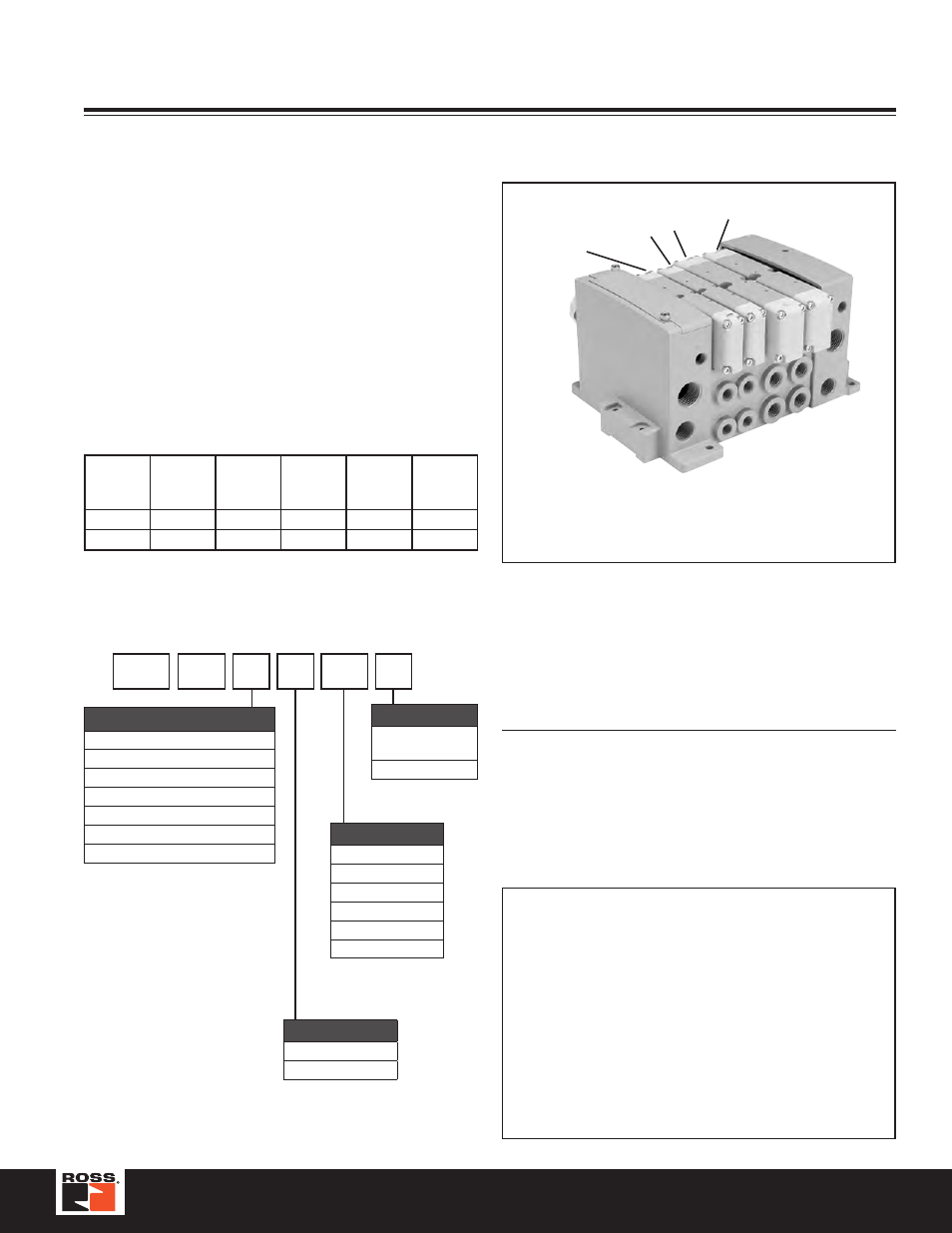
Example:
4-Station Manifold with (2) Size 00 (18mm) and
(2) Size 0 (26mm) Valves On Manifold Bases
Size
00 & 0
Voltage
Code
25-Pin
D-Sub
19-Pin
Round
Single
12-Pin
M23
Serial
Bus
24VDC
W
24
16
8
32
120VAC*
Z
24
16
8
32
* Not CSA certified for 25-Pin, D-Sub option.
Manifold Assembly Model Number
How To Order Manifold Assemblies
When using a Series W66, Size 0 or Series W66, Size 00 manifold base with the
“N” Enclosure / Lead Length option:
• Outputs 1 – 24 can be single or double address bases. Use a base with “J” or
“M” Enclosure / Lead Length option.
• Outputs 25 – 26 are a single address base. Use a base with “N” Enclosure /
Lead Length option (this is a single address board with a ribbon connection
from the valve driver module, RPSSV32A).
• Outputs 27 – 32 can be single or double. Use a base with “J” or “M”
Enclosure / Lead Length option.
When using an Series W66, Size 0 or Series W66, Size 00 manifold base with
the “P” Enclosure / Lead Length option:
• Outputs 1 – 24 can be single or double address bases. Use a base with “J” or
“M” Enclosure / Lead Length option.
• Outputs 25 – 28 are a double address base. Use a base with “P” Enclosure /
Lead Length option (this is a double address board with a ribbon connection
from the valve driver module, RPSSV32A).
• Outputs 29 – 32 can be single or double. Use a base with “J” or “M”
Enclosure / Lead Length option.
AA 00 D 0 04
–
Number of Stations*
02
04
•
24
•
32
†
* Must be ordered in
multiples of (2).
† Maximum Number
Port Type
0
NPT
1
BSPP “G”
End Plate Type
25-Pin D
19-Pin E
16 Point Terminal Strip F
M23, 12-Pin G
Standard - Non-Collective Wiring S
4-Pin, M12, Connector 15407-1 U**
Serial Bus Y*
* Valve Driver Module included. Must order
communication modules separately.
** Must be used with Valve Series 02 & 01.
Transition Plate
Blank No Transition
Plate
B*
00 / 0 to H2
* Not Available with
End Plate Type “U”.
Manifolds — Series W66