Technical & wiring information, Wiring, Point terminal strip – Ross Controls ROSS MODULAR I User Manual
Page 31: Subbase wiring manifold wiring, I/o addressing examples, Connections, 14 solenoid 12 solenoid
31
www.rosscontrols.com
Technical & Wiring Information
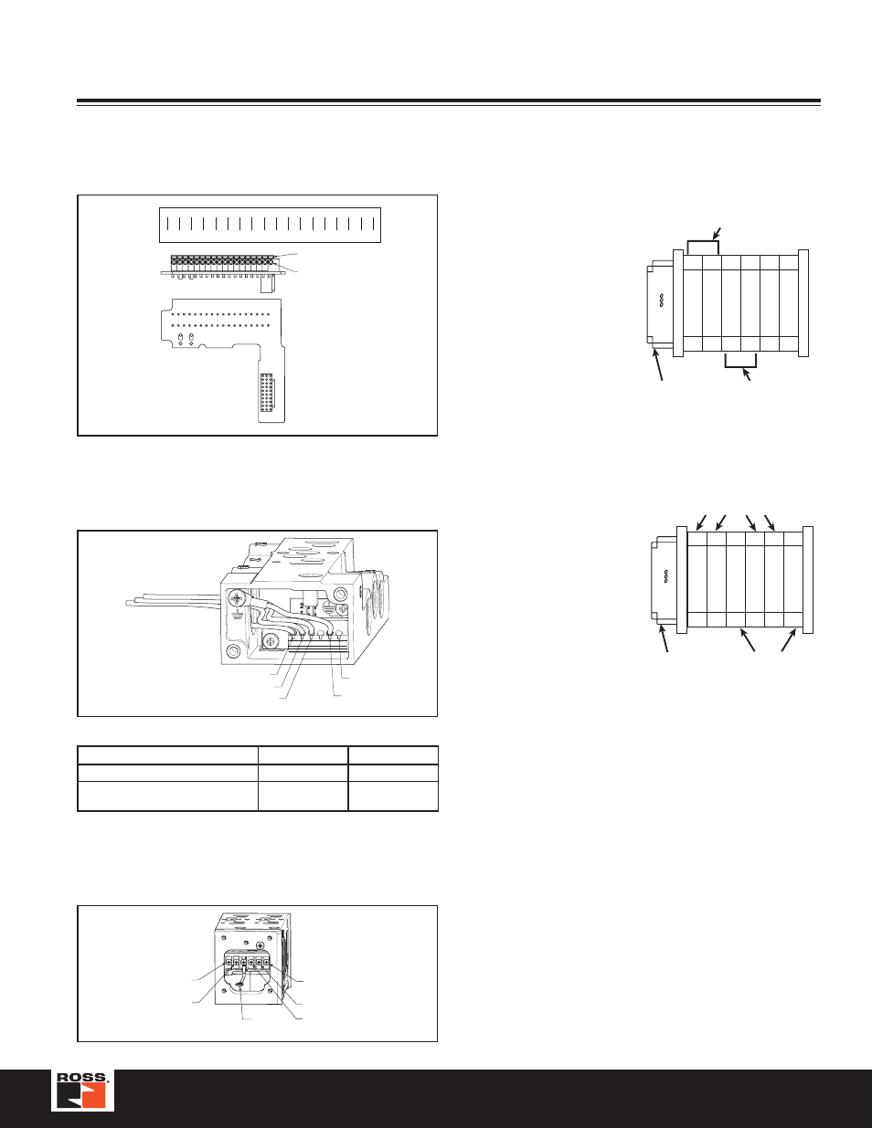
16-Point Terminal Strip
Terminal
Valve
Solenoid
G
G C 1 2 3 4 5 6 7 8 9 10 111213 1415 16
C
1
2
3
4
5
6
7
8
9 10 11 12 13 14 15 16
GND COM 1
2
3
4
5
6
7
8
9 10 11 12 13 14 15 16
Push Orange Lever
with Screwdriver
Insert Wire into Hole.
Strip Length 10mm.
Use 18-22 AWG Wire.
Connections
14 Solenoid
12 Solenoid
Valves with Wires
Black Wires
Red Wires
Valves with Terminal Block (Will
accept 18 to 24 Gauge Wires)
14 and Com
Terminals
12 and Com
Terminals
Comm
12 Terminal
14 Terminal
Ground
(Parker)
Ground
(Customer)
4
3
Subbase Wiring
Manifold Wiring
Ground
(Customer)
12B
14B
14A
12A
Common
I/O Addressing Examples
Size1, 2 & 3 Example:
Single Station Manifold Bases
Notes:
SS = Single Solenoid Valve
DS = Double Solenoid Valve
First output address the #14 end of the valve closest to the valve
driver module.
Size 00 & 0 Example
Two Station Manifold Bases
Double Addressed
Manifold
(Option M)
Single Addressed
Manifold
(Option J)
8
10
7
9
1
14-end
5
6
3
12-end
2
4
DS
DS
SS
DS
DS
SS
Valve Driver
Module
(RPSSV32A)
Valve Driver
Module
(RPSSV32A)
Double Address
Circuit Board
(Option M)
Single Address
Circuit Board
(Option J)
7
9
8
10
1
14-end
5
6
3
12-end
2
4
DS
DS
SS
SS
DS
DS
Wiring