Ross Controls 5599_I SPOOL & SLEEVE SERIES W60 User Manual
Series w60 spool valves, Solenoid control, Iso 5599/i - drop cord connections
ROSS CONTROLS
®
6
0.9
1.9
3.9
0.9
1.9
3.9
0.9
1.9
3.9
0.9
1.9
3.9
1
2
3
1
2
3
1
2
3
1
2
3
W6076B2401
W6076B3401
W6076B4401
W6076B2407
W6076B3407
W6076B4407
W6077B2401
W6077B3401
W6077B4401
W6077B2407
W6077B3407
W6077B4407
29
41
51
17
20
20
30
40
50
30
40
50
3.5
1.5
0.8
3.5
1.5
0.8
3.5
1.5
0.8
3.5
1.5
0.8
4.9
2.4
1.1
5.0
2.5
1.1
5.0
2.5
1.1
5.0
2.5
1.1
1.5 (0.7)
2.0 (1.0)
3.5 (1.6)
2.0 (1.0)
2.5 (1.2)
4.0 (1.9)
2.0 (1.0)
2.5 (1.2)
4.0 (1.9)
2.0 (1.0)
2.5 (1.2)
4.0 (1.9)
5.4 (137)
6.2 (158)
5.9 (150)
6.7 (170)
7.5 (191)
6.0 (152)
6.7 (170)
7.7 (196)
6.2 (158)
6.7 (170)
7.7 (196)
6.2 (158)
1.7 (42)
2.1 (54)
2.6 (65)
17 (42)
2.1 (54)
2.6 (65)
1.7 (42)
2.1 (54)
2.6 (65)
1.7 (42)
2.1 (54)
2.6 (65)
4.4 (112)
4.7 (119)
4.9 (124)
4.4 (112)
4.7 (119)
4.9 (124)
4.4 (112)
4.7 (119)
4.9 (124)
4.4 (112)
4.7 (119)
4.9 (124)
Valve Model
Number
§
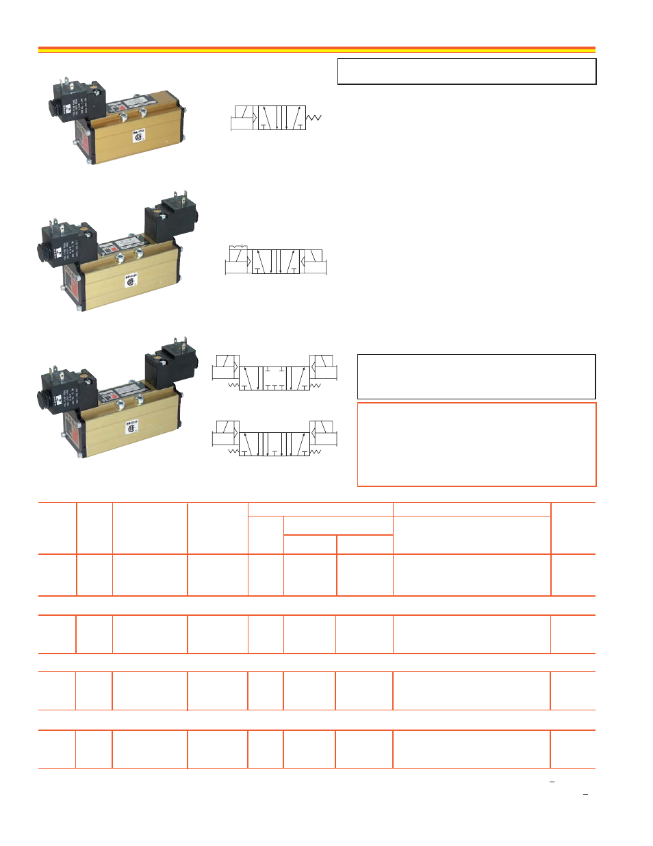
5/2 SINGLE SOLENOID PILOT VALVES
5/2 DOUBLE SOLENOID PILOT VALVES
Avg. Response Constants**
Dimensions
inches (mm)
F
M
Out-Exh.
In-Out
Weight
lb (kg)
Avg.
Cv
ISO
Size
Length
Width
Height
†
SERIES
W60
SPOOL VALVES –
Solenoid Control
1 3
4
2
5
12
14
1 3
4
2
5
12
14
1 3
4
2
5
12
14
1 3
4
2
5
12
14
STANDARD SPECIFICATIONS
Solenoids:
Rated for continuous duty.
Standard voltages: 100–110 volts 50 Hz.; 100–120
volts 60 Hz.; 24, 110 volts d.c.
Power Consumption:
8.5 VA inrush; 6 VA holding
on 50 or 60 Hz.; 6 watts on d.c.
Ambient Temperature:
40 to 120° F (4 to 50° C).
Media Temperature:
40 to 175° F (4 to 80° C).
Flow Media:
5 micron filtered air.
Inlet Pressure:
Vacuum to 150 psig (10 bar).
Pilot Pressure:
Size 1: At least 30 psig (2 bar).
Size 2 and 3: At least 15 psig (1 bar).
OPTIONS
Sub-Bases & Manifolds:
Page 14.
Connectors, Electrical:
Page 15.
Regulators & Flow Controls, Interposed:
Page 15.
Locking Overrides:
See note below.
§
GM PS-1 models with 3-pin mini-connectors:
See
note below.
Port
Sizes*
1/8 – 3/8
3/8 – 1/2
1/2 – 3/4
1/8 – 3/8
3/8 – 1/2
1/2 – 3/4
1/8 – 3/8
3/8 – 1/2
1/2 – 3/4
1/8 – 3/8
3/8 – 1/2
1/2 – 3/4
5/2 Single Solenoid Pilot Valve
5/2 Double Solenoid Pilot Valve
5/3 Open or Closed Center Valve
5/3 CLOSED CENTER DOUBLE SOLENOID PILOT VALVES
5/3 OPEN CENTER DOUBLE SOLENOID PILOT VALVES
IMPORTANT NOTE
Please read carefully and thoroughly the
CAUTIONS
on page 23.
**VALVE RESPONSE TIME (msec) = M + (F • V)
Average time required to fill volume V (cubic inches)
to 90% of supply pressure or to exhaust it to 10%
of supply pressure. M and F values are shown in
charts for each valve. See discussion of
Valve
Response Time
on page 22.
Closed Center
Open Center
§
Models with locking overrides can be ordered by changing the 9th digit of model number to “1”. For example, W6076B2411.
For models with 3-pin mini-connectors that conform to G.M. PS-1 standards, change the 9th digit to “3”. For example, W6076B2431.
* Port sizes determined by customer’s choice of base or manifold. Bases and manifolds sold separately – see page 14.
†
Height of valve with electrical connector installed. Connectors sold separately – see page 15.
ISO 5599/I - Drop Cord Connections