Agilent w1314a receivers – Agilent Technologies Wireless Network Optimization Platform E6474A User Manual
Page 142
142
Agilent E6474A User’s Guide
B
Connection Panels and LED Indicators
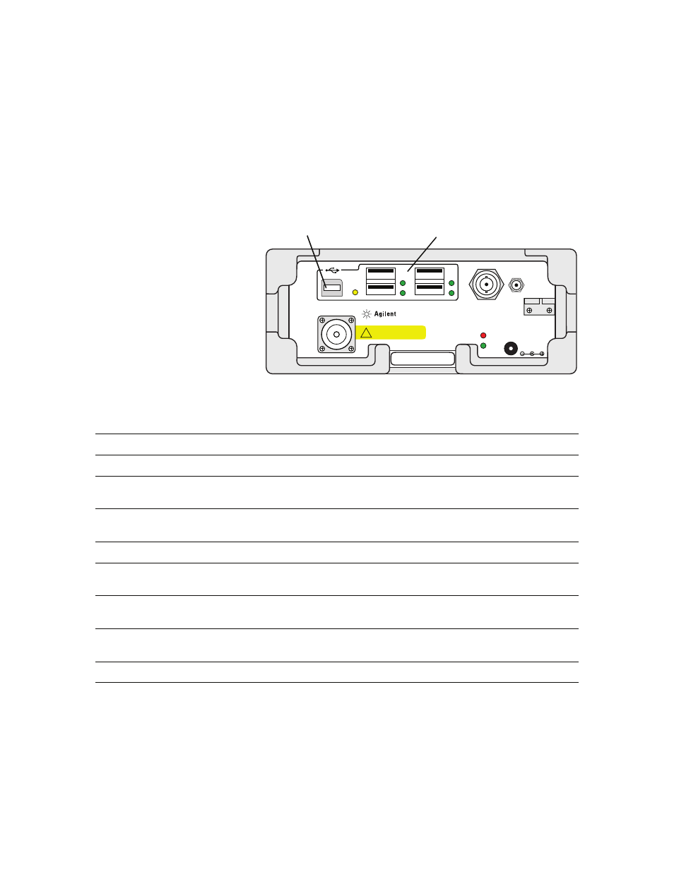
Agilent W1314A Receivers
Figure 108 W1314A Receiver Front Panel
Table 2
W1314A Receiver connection descriptions
RF IN
W1314A-120
Quad Band Receiver
9-34VDC
18W TYP
48W MAX
GPS
ANT.
GPS
1PPS
TEMP
STAT
450-496, 921-962 MHz
1800-1885, 2100-2180 MHz
+10 dBm (10 mW) MAX
20 VDC MAX
!
Master USB port
4-port USB hub
Reference
Name
Description or Cable Connection
Master USB port
None
This port is used to connect your W1314A receiver to your laptop.
4-port USB hub
None
Used for connecting phones, USB license dongles or multiple
receivers (
“Connecting multiple W1314A receivers"
GPS 1PPS
GPS timing port
Connect a pulse source (GPS 1PPS) to provide a timing pulse for
measurement synchronization when a GPS signal is not available.
GPS Ant.
GPS antenna connector
Connect to GPS antenna.
Temp
Temperature LED
Displays a warning when the receiver temperature is over limit.
Refer to the online help for more information on W1314A LED status.
Stat
Power Status LED
Displays the power connection and receiver firmware status. Refer
to the online help for more information on W1314A LED status.
9-34 VDC
Power input
Connect to Receiver Power cable. Use the cable clamp block to
prevent the power cable from being accidentally pulled out.
RF Input
RF antenna connector
Connect to receiver’s RF antenna.