Signal and input power, Symbols, Signal and input power symbols – Agilent Technologies Wireless Network Optimization Platform E6474A User Manual
Page 137
Safety and Regulatory Information
A
Agilent E6474A User’s Guide
137
Signal and input power
Symbols
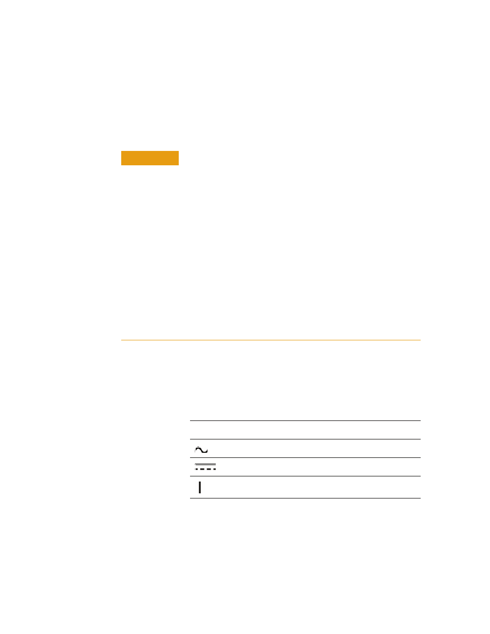
Table 1
lists standard symbols that appear on equipment
panels.
Table 1
Equipment panel symbols
CAUTION
The input power to the Agilent 645xC digital receiver should not
exceed –15 dBm. Power levels greater than +10 dBm will damage the
instrument.
For continued protection against fire hazard, replace the line fuse
(cigarette lighter/2 amp 32 V FB fuse - 645xC, 4 amp 32 V FB Fuse -
W1314A) only with the same type of rating (type nA/nV). The use of
other fuses or materials is prohibited.
If you use external power, install the instrument so the detachable
power cord is readily identifiable and is easily reached by the operator.
The detachable power cord is the instrument disconnecting device. It
disconnects the mains circuit from the mains supply before other parts
of the instrument.
If you do not use external power, position the product so you can easily
operate the disconnecting device.
Always use the power cords supplied with this product. Failure to
ensure adequate earth grounding by not using this cord may cause
product damage.
Symbol
Description
AC power input
DC power input
Power switch ON position