Teledyne LeCroy PETracer ML Analyzer and Exerciser User Manual User Manual
Page 41
PETracer ML User Manual
Chapter 3: Installation
Teledyne LeCroy
33
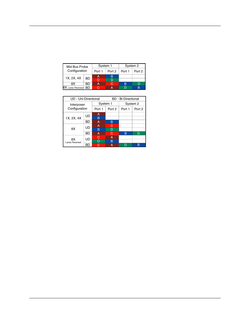
The smaller connectors are labeled A, B, C, and D. Each transmits four physical lanes of
traffic in one direction (shown in the illustration on the right). This means that to record
bidirectional traffic you must use at least two of the small connectors: one to capture the
transmit traffic and one to capture the receive traffic (with respect to one of the devices).
The various configurations of connectors and link widths are shown in the table below.
Connecting the Interposer Data Cable
To connect the Interposer data cable:
Step 1 Insert the large connector of the Interposer data cable [c] or [d] into the
Interposer’s data connector located on the metal face plate of the
Interposer [e].
Step 2 Connect the small connectors of the Interposer data cable [c] or [d] to the
Analyzer probe data connectors [a] and, if needed, [b] on the front of the
Analyzer. The number of connectors you use depends on the width and
direction of the link you are attempting to monitor. See foregoing table to
determine the appropriate number of connectors for your test.
Connect USB Cable and Power on the Analyzer and DUTs
Step 1 Connect the provided USB cable between the UPAS 10000 Analyzer
and the host machine that runs the PETracer ML software.
Step 2 Power on the UPAS10000 Analyzer. The Analyzer's green power LED
lights, and the red status LED turns on for approximately 20 seconds
while the Analyzer performs self-diagnostics.
Step 3 After the Analyzer's red status LED turns off, power on the PCI Express
system under test.
Step 4 Open the PETracer ML software on the host machine. The Analyzer is
now ready for PCI Express traffic recording.