8 rear panel description – Teledyne LeCroy PETracer ML Analyzer and Exerciser User Manual User Manual
Page 24
Chapter 2: Hardware Description
PETracer ML User Manual
16
Teledyne LeCroy
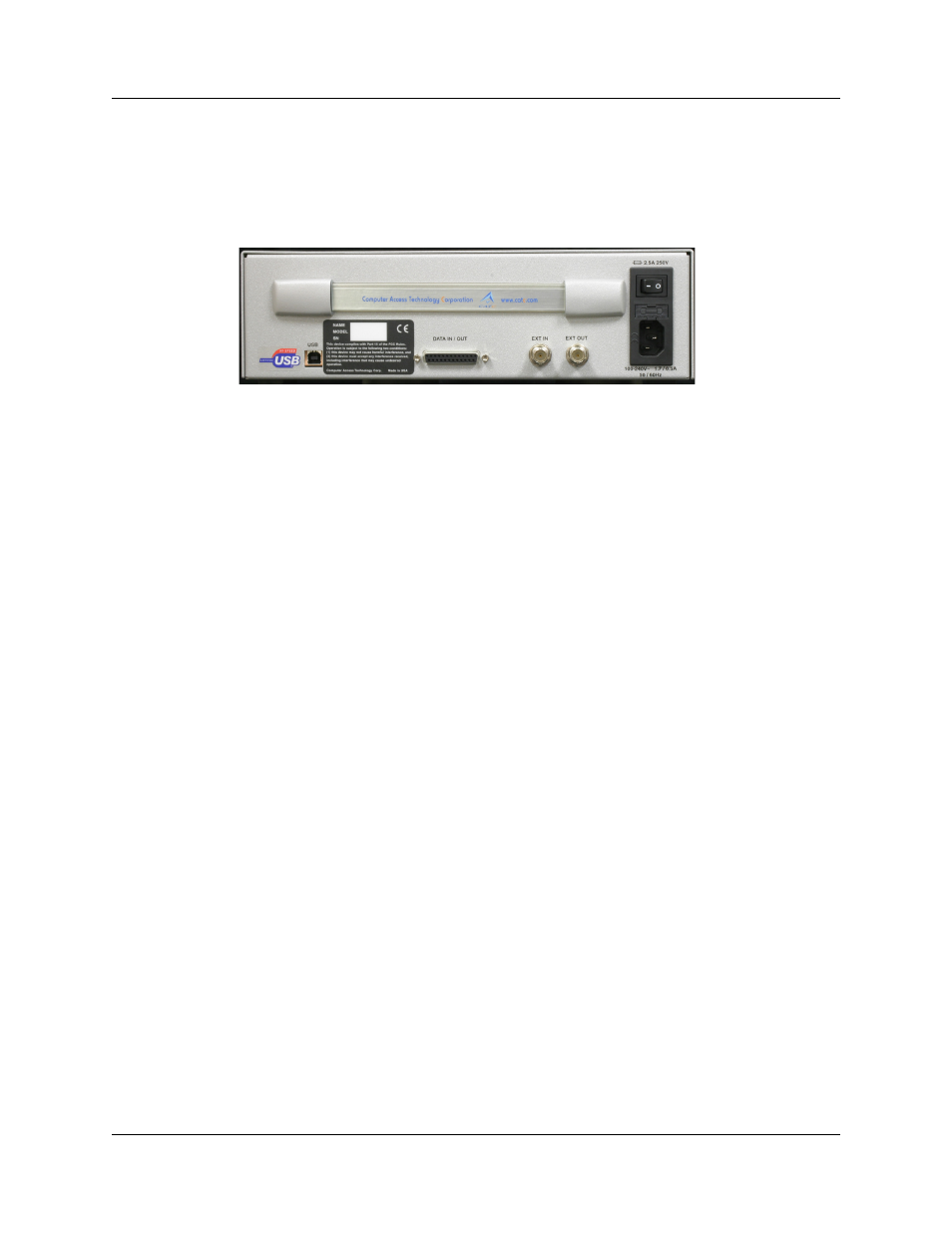
2.8 Rear Panel Description
From left to right, the UPAS rear panel contains the following components:
Figure 2.1 PETracer ML Rear Panel
USB Type B Host Machine Connector
This connector links the Analyzer to the host machine for the purpose of transmitting
commands from the host machine to the Analyzer and uploading CATC Traces from the
Analyzer’s recording memory to the PETracer software for viewing and analysis or links
the PETrainer Exerciser to the host machine for the purpose of downloading scripts and
controlling the behavior of the Exerciser.
RS-232 25-pin Data Input/Output Connector
This connector links a 25 pin RS-232 cable to an external Breakout Board. The
Breakout Board allows signals to be sent from the Exerciser or Analyzer to an external
device such as an oscilloscope or from an external device to the Exerciser or Analyzer
for the purpose of triggering on an external input. You configure input/output signalling
through the Recording Options dialog box. The Breakout Board use is described at the
end of this chapter.
RS-232 40-pin Data Input/Output Connector
This connector links a 40 pin RS-232 cable to an external Breakout Board. The
Breakout Board allows signals to be sent from the Analyzer to an external device such
as an oscilloscope or from an external device to the Analyzer for the purpose of triggering
on an external input. You configure input/output signalling through the Recording Options
dialog box. Breakout Board use is described at the end of this chapter.