IAI America RCA2-TW4N User Manual
Page 117
109
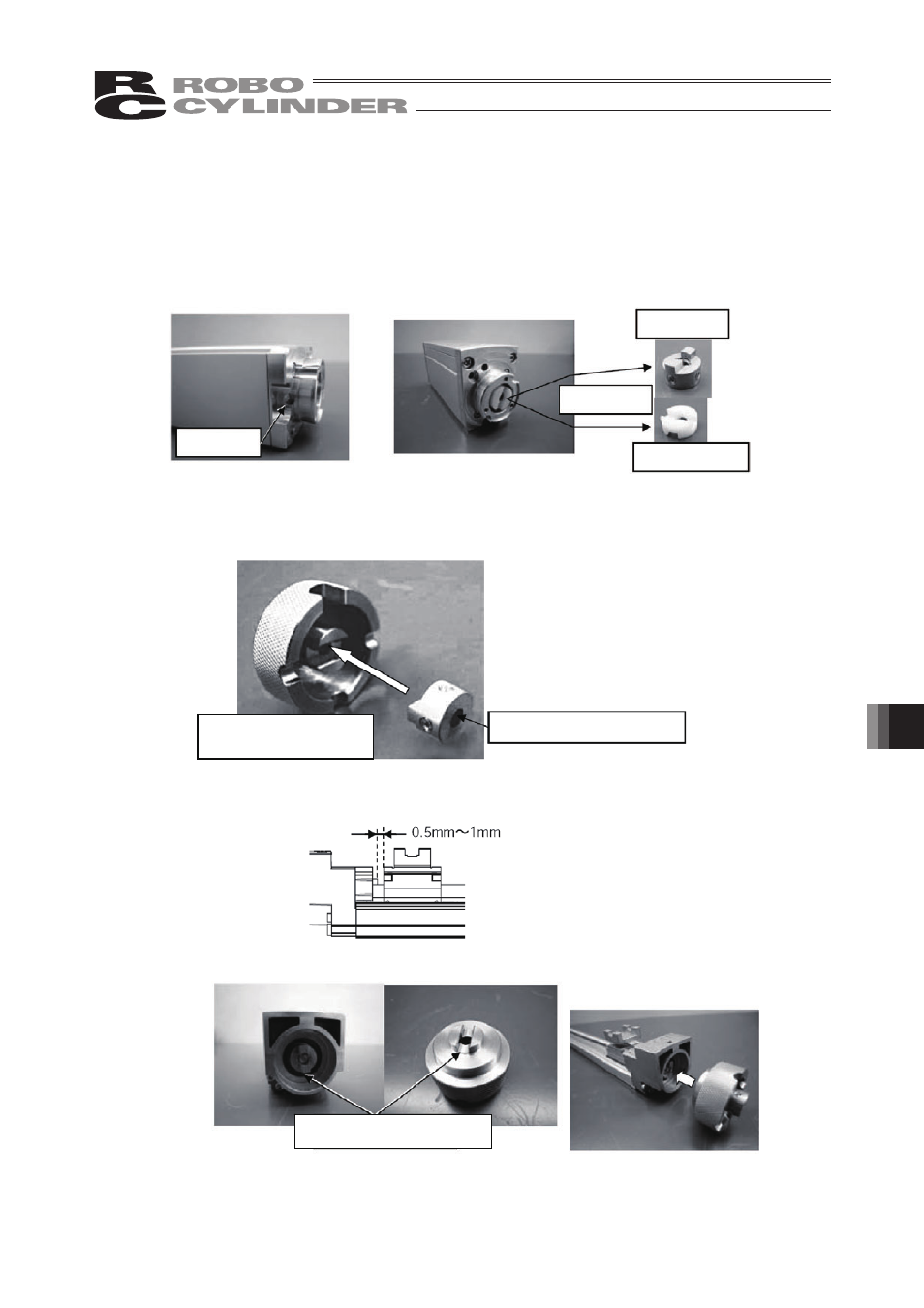
13. Maintenance and Inspection
[3] Take out the coupling hub and coupling spacer from the detached motor unit. Twist the coupling hub
or coupling spacer on the motor side to align the screw holes with the hole for the tool to go through.
Then remove two screws with a 2 mm hex wrench.
* If there is only a coupling hub on the motor unit side, then there is a coupling spacer on the
actuator side which can be removed by pulling.
* If both coupling hub and coupling spacer are present, pull them apart.
(They should separate with a gentle pull.)
[4] Fit the protruding part of the coupling hub into the groove of the dedicated replacement jig (large),
and temporarily hold them together with two M3x3 Allen screws (tighten just enough so that the
coupling hub does not fall off).
[5] Turn the shaft to move the table about 0.5 mm to 1 mm from the mechanical end on the home
position side.
[6] Fit the groove of the dedicated replacement jig (large) assembled in [4] over the protrusion of the
actuator.
Fit groove over protrusion
Hole for tool
Pull apart
Coupling hub
Coupling spacer
Dedicated replacement
jig (large)
Line up holes in center