Ceramic seal replacement – Ransburg No. 2 Air Motor Atex Approved Unit 80086-XX User Manual
Page 42
AH
AH
AH
AH----12
12
12
12----01.03 No. 2 Air Motor Handgun
01.03 No. 2 Air Motor Handgun
01.03 No. 2 Air Motor Handgun
01.03 No. 2 Air Motor Handgun
42
42
42
42
2. Tilt the Barrel (Item 3) so the rear opening is
2. Tilt the Barrel (Item 3) so the rear opening is
2. Tilt the Barrel (Item 3) so the rear opening is
2. Tilt the Barrel (Item 3) so the rear opening is
down. The resistor (Item 1) and the spring
down. The resistor (Item 1) and the spring
down. The resistor (Item 1) and the spring
down. The resistor (Item 1) and the spring
(Item 2) should fall out of the drive shaft.
(Item 2) should fall out of the drive shaft.
(Item 2) should fall out of the drive shaft.
(Item 2) should fall out of the drive shaft.
3. Measure the resistance of the resistor (Item
3. Measure the resistance of the resistor (Item
3. Measure the resistance of the resistor (Item
3. Measure the resistance of the resistor (Item
2) using a MegOhm meter with leads placed
2) using a MegOhm meter with leads placed
2) using a MegOhm meter with leads placed
2) using a MegOhm meter with leads placed
end to end. The resistance should be between
end to end. The resistance should be between
end to end. The resistance should be between
end to end. The resistance should be between
11,000 to 9,000
11,000 to 9,000
11,000 to 9,000
11,000 to 9,000 M
M
M
MΩ.
Ω.
Ω.
Ω.
If the resistor is outside of
If the resistor is outside of
If the resistor is outside of
If the resistor is outside of
this range, it must be replaced, or there is a
this range, it must be replaced, or there is a
this range, it must be replaced, or there is a
this range, it must be replaced, or there is a
large hole in the center of the spray pattern.
large hole in the center of the spray pattern.
large hole in the center of the spray pattern.
large hole in the center of the spray pattern.
4.
4.
4.
4. Install the ground resistor (Item 2) and spring
Install the ground resistor (Item 2) and spring
Install the ground resistor (Item 2) and spring
Install the ground resistor (Item 2) and spring
(Item 1) back into the drive shaft. Install the ca-
(Item 1) back into the drive shaft. Install the ca-
(Item 1) back into the drive shaft. Install the ca-
(Item 1) back into the drive shaft. Install the ca-
ble/motor assembly per "Cable Assembly Re-
ble/motor assembly per "Cable Assembly Re-
ble/motor assembly per "Cable Assembly Re-
ble/motor assembly per "Cable Assembly Re-
placement" in the "Maintenance" section.
placement" in the "Maintenance" section.
placement" in the "Maintenance" section.
placement" in the "Maintenance" section.
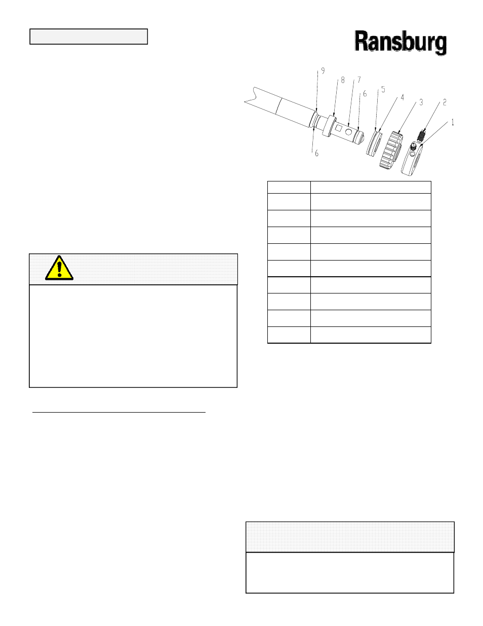
Ceramic Seal Replacement
Ceramic Seal Replacement
Ceramic Seal Replacement
Ceramic Seal Replacement
(Refer to Figure 26)
(Refer to Figure 26)
(Refer to Figure 26)
(Refer to Figure 26)
1. Unscrew nut (Item 3) and pull the drive shaft
1. Unscrew nut (Item 3) and pull the drive shaft
1. Unscrew nut (Item 3) and pull the drive shaft
1. Unscrew nut (Item 3) and pull the drive shaft
(Item 7) with all ceramic seal components at-
(Item 7) with all ceramic seal components at-
(Item 7) with all ceramic seal components at-
(Item 7) with all ceramic seal components at-
tached out of the barrel.
tached out of the barrel.
tached out of the barrel.
tached out of the barrel.
2. Remove the O
2. Remove the O
2. Remove the O
2. Remove the O----rings (Item 6) from the drive
rings (Item 6) from the drive
rings (Item 6) from the drive
rings (Item 6) from the drive
shaft, taking care not to damage the drive shaft.
shaft, taking care not to damage the drive shaft.
shaft, taking care not to damage the drive shaft.
shaft, taking care not to damage the drive shaft.
3. Using a screwdriver, loosen the two set
3. Using a screwdriver, loosen the two set
3. Using a screwdriver, loosen the two set
3. Using a screwdriver, loosen the two set
screws (Item 2) (about two turns counterclock-
screws (Item 2) (about two turns counterclock-
screws (Item 2) (about two turns counterclock-
screws (Item 2) (about two turns counterclock-
wise) of the collar (Item 1) and remove the col-
wise) of the collar (Item 1) and remove the col-
wise) of the collar (Item 1) and remove the col-
wise) of the collar (Item 1) and remove the col-
lar and nut (Item 3) from the drive shaft.
lar and nut (Item 3) from the drive shaft.
lar and nut (Item 3) from the drive shaft.
lar and nut (Item 3) from the drive shaft.
4.Slide outer ceramic seal (Item 5) and inner
4.Slide outer ceramic seal (Item 5) and inner
4.Slide outer ceramic seal (Item 5) and inner
4.Slide outer ceramic seal (Item 5) and inner
PTFE seal (Item 6) off the drive shaft .
PTFE seal (Item 6) off the drive shaft .
PTFE seal (Item 6) off the drive shaft .
PTFE seal (Item 6) off the drive shaft .
5. Remove the remaining two O
5. Remove the remaining two O
5. Remove the remaining two O
5. Remove the remaining two O----rings (Items 4
rings (Items 4
rings (Items 4
rings (Items 4
and 9) from the drive shaft .
and 9) from the drive shaft .
and 9) from the drive shaft .
and 9) from the drive shaft .
6. Discard the ceramic seal (Item 5), PTFE
6. Discard the ceramic seal (Item 5), PTFE
6. Discard the ceramic seal (Item 5), PTFE
6. Discard the ceramic seal (Item 5), PTFE
seal (Item 8), O
seal (Item 8), O
seal (Item 8), O
seal (Item 8), O----rings (Items 4,6 and 9). Exam-
rings (Items 4,6 and 9). Exam-
rings (Items 4,6 and 9). Exam-
rings (Items 4,6 and 9). Exam-
ine the drive shaft and replace if damaged.
ine the drive shaft and replace if damaged.
ine the drive shaft and replace if damaged.
ine the drive shaft and replace if damaged.
7. Slide O
7. Slide O
7. Slide O
7. Slide O----ring (Item 10) over drive shaft until it
ring (Item 10) over drive shaft until it
ring (Item 10) over drive shaft until it
ring (Item 10) over drive shaft until it
bottoms on shoulder. Install O
bottoms on shoulder. Install O
bottoms on shoulder. Install O
bottoms on shoulder. Install O----ring (Item 6)
ring (Item 6)
ring (Item 6)
ring (Item 6)
into second O
into second O
into second O
into second O----ring groove of drive shaft.
ring groove of drive shaft.
ring groove of drive shaft.
ring groove of drive shaft.
C A U T I O N
C A U T I O N
C A U T I O N
C A U T I O N
DO NOT Apply Dielectric Grease
DO NOT Apply Dielectric Grease
DO NOT Apply Dielectric Grease
DO NOT Apply Dielectric Grease to the
to the
to the
to the
Resistor (Item 2), Spring (Item 1), or In-
Resistor (Item 2), Spring (Item 1), or In-
Resistor (Item 2), Spring (Item 1), or In-
Resistor (Item 2), Spring (Item 1), or In-
side and Outside Diameters of the Drive
side and Outside Diameters of the Drive
side and Outside Diameters of the Drive
side and Outside Diameters of the Drive
Shaft .
Shaft .
Shaft .
Shaft .
The application of dielectric grease or
The application of dielectric grease or
The application of dielectric grease or
The application of dielectric grease or
any other lubricant to these compo-
any other lubricant to these compo-
any other lubricant to these compo-
any other lubricant to these compo-
nents can cause premature failure of
nents can cause premature failure of
nents can cause premature failure of
nents can cause premature failure of
the motor.
the motor.
the motor.
the motor.
Item #
Item #
Item #
Item # Description
Description
Description
Description
1
1
1
1
Collar
Collar
Collar
Collar
2
2
2
2
Set Screw (2) required
Set Screw (2) required
Set Screw (2) required
Set Screw (2) required
3
3
3
3
Nut
Nut
Nut
Nut
4
4
4
4
O
O
O
O----ring
ring
ring
ring
5
5
5
5
Seal, Outer Ceramic
Seal, Outer Ceramic
Seal, Outer Ceramic
Seal, Outer Ceramic
6
6
6
6
O
O
O
O----ring (2) required
ring (2) required
ring (2) required
ring (2) required
7
7
7
7
Shaft , Drive
Shaft , Drive
Shaft , Drive
Shaft , Drive
8
8
8
8
Seal, Inner, PTFE
Seal, Inner, PTFE
Seal, Inner, PTFE
Seal, Inner, PTFE
9
9
9
9
O
O
O
O----ring
ring
ring
ring
Figure 26: Ceramic Seal Replacement
Figure 26: Ceramic Seal Replacement
Figure 26: Ceramic Seal Replacement
Figure 26: Ceramic Seal Replacement
NOTE
NOTE
NOTE
NOTE
Lightly lubricate the O
Lightly lubricate the O
Lightly lubricate the O
Lightly lubricate the O----rings only with
rings only with
rings only with
rings only with petroleum
petroleum
petroleum
petroleum
jelly. DO NOT USE SILICONE LUBRICANTS!
jelly. DO NOT USE SILICONE LUBRICANTS!
jelly. DO NOT USE SILICONE LUBRICANTS!
jelly. DO NOT USE SILICONE LUBRICANTS!
MAINTENANCE
MAINTENANCE
MAINTENANCE
MAINTENANCE