Operation, Procedures – Ransburg No. 2 Air Motor Atex Approved Unit 80086-XX User Manual
Page 21
21
21
21
21
AH
AH
AH
AH----12
12
12
12----01.03 No. 2 Air Motor Handgun
01.03 No. 2 Air Motor Handgun
01.03 No. 2 Air Motor Handgun
01.03 No. 2 Air Motor Handgun
OPERATION
OPERATION
OPERATION
OPERATION
PROCEDURES
PROCEDURES
PROCEDURES
PROCEDURES
Prior to operating the No. 2 Handgun, ensure
Prior to operating the No. 2 Handgun, ensure
Prior to operating the No. 2 Handgun, ensure
Prior to operating the No. 2 Handgun, ensure
that the equipment is installed properly (see
that the equipment is installed properly (see
that the equipment is installed properly (see
that the equipment is installed properly (see
"Installation" section of this service manual).
"Installation" section of this service manual).
"Installation" section of this service manual).
"Installation" section of this service manual).
Observe and follow the safety requirements at
Observe and follow the safety requirements at
Observe and follow the safety requirements at
Observe and follow the safety requirements at
ALL times.
ALL times.
ALL times.
ALL times.
1. Inspect the rotating bell assembly to ensure
1. Inspect the rotating bell assembly to ensure
1. Inspect the rotating bell assembly to ensure
1. Inspect the rotating bell assembly to ensure
that it is clean and is not chipped. Replace or
that it is clean and is not chipped. Replace or
that it is clean and is not chipped. Replace or
that it is clean and is not chipped. Replace or
clean the bell assembly when necessary.
clean the bell assembly when necessary.
clean the bell assembly when necessary.
clean the bell assembly when necessary.
2. Set the paint fluid pressure at 0.2 to 0.3 bar
2. Set the paint fluid pressure at 0.2 to 0.3 bar
2. Set the paint fluid pressure at 0.2 to 0.3 bar
2. Set the paint fluid pressure at 0.2 to 0.3 bar
(3 to 4 psi ). Adjust the pressure up or down for
(3 to 4 psi ). Adjust the pressure up or down for
(3 to 4 psi ). Adjust the pressure up or down for
(3 to 4 psi ). Adjust the pressure up or down for
the desired fluid delivery. Higher fluid pressure
the desired fluid delivery. Higher fluid pressure
the desired fluid delivery. Higher fluid pressure
the desired fluid delivery. Higher fluid pressure
may be needed with higher viscosity material,
may be needed with higher viscosity material,
may be needed with higher viscosity material,
may be needed with higher viscosity material,
longer hoses, or higher fluid deliveries.
longer hoses, or higher fluid deliveries.
longer hoses, or higher fluid deliveries.
longer hoses, or higher fluid deliveries.
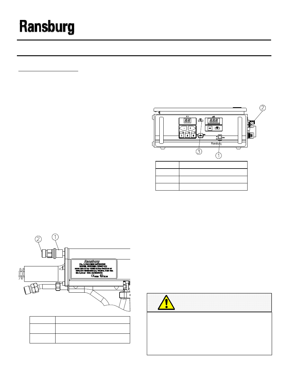
3. Set the slide valve switch on the applicator to
3. Set the slide valve switch on the applicator to
3. Set the slide valve switch on the applicator to
3. Set the slide valve switch on the applicator to
the “OFF” position as shown in Figure 12. The
the “OFF” position as shown in Figure 12. The
the “OFF” position as shown in Figure 12. The
the “OFF” position as shown in Figure 12. The
Slide Valve will be pulled back against the inlet
Slide Valve will be pulled back against the inlet
Slide Valve will be pulled back against the inlet
Slide Valve will be pulled back against the inlet
air fitting.
air fitting.
air fitting.
air fitting.
Item #
Item #
Item #
Item # Description
Description
Description
Description
1
1
1
1
Slide Valve
Slide Valve
Slide Valve
Slide Valve----”OFF” Position
”OFF” Position
”OFF” Position
”OFF” Position
2
2
2
2
Air Inlet Fitting
Air Inlet Fitting
Air Inlet Fitting
Air Inlet Fitting
Figure 12: Slide Valve “Off” Position
Figure 12: Slide Valve “Off” Position
Figure 12: Slide Valve “Off” Position
Figure 12: Slide Valve “Off” Position
Item #
Item #
Item #
Item # Description
Description
Description
Description
1
1
1
1
Power ‘ON
Power ‘ON
Power ‘ON
Power ‘ON ---- OFF” Switch
OFF” Switch
OFF” Switch
OFF” Switch
2
2
2
2
Flow Switch Fitting
Flow Switch Fitting
Flow Switch Fitting
Flow Switch Fitting
3
3
3
3
HV on Indicator
HV on Indicator
HV on Indicator
HV on Indicator
Figure 13: 9060 Power “ON
Figure 13: 9060 Power “ON
Figure 13: 9060 Power “ON
Figure 13: 9060 Power “ON----OFF” Switch
OFF” Switch
OFF” Switch
OFF” Switch
5. Push the slide valve switch on the applicator
5. Push the slide valve switch on the applicator
5. Push the slide valve switch on the applicator
5. Push the slide valve switch on the applicator
forward toward the applicator barrel. The air motor
forward toward the applicator barrel. The air motor
forward toward the applicator barrel. The air motor
forward toward the applicator barrel. The air motor
will begin turning and voltage will be present at the
will begin turning and voltage will be present at the
will begin turning and voltage will be present at the
will begin turning and voltage will be present at the
bell. The HV On indicator on the 9060 will illumi-
bell. The HV On indicator on the 9060 will illumi-
bell. The HV On indicator on the 9060 will illumi-
bell. The HV On indicator on the 9060 will illumi-
nate when voltage is on. Figure 14 shows the
nate when voltage is on. Figure 14 shows the
nate when voltage is on. Figure 14 shows the
nate when voltage is on. Figure 14 shows the
speed versus inlet air pressure with the applicator
speed versus inlet air pressure with the applicator
speed versus inlet air pressure with the applicator
speed versus inlet air pressure with the applicator
triggered. This chart may be used to assist with
triggered. This chart may be used to assist with
triggered. This chart may be used to assist with
triggered. This chart may be used to assist with
initial pressure settings .
initial pressure settings .
initial pressure settings .
initial pressure settings .
6.
6.
6.
6. Hold the No. 2 handgun perpendicular to, and
Hold the No. 2 handgun perpendicular to, and
Hold the No. 2 handgun perpendicular to, and
Hold the No. 2 handgun perpendicular to, and
13 to 18 cm (4 to 7 inches ) from the part being
13 to 18 cm (4 to 7 inches ) from the part being
13 to 18 cm (4 to 7 inches ) from the part being
13 to 18 cm (4 to 7 inches ) from the part being
coated. Trigger the handgun and observe the at-
coated. Trigger the handgun and observe the at-
coated. Trigger the handgun and observe the at-
coated. Trigger the handgun and observe the at-
omization of the coating
omization of the coating
omization of the coating
omization of the coating
material.
material.
material.
material.
C A U T I O N
C A U T I O N
C A U T I O N
C A U T I O N
The application process works best when the
The application process works best when the
The application process works best when the
The application process works best when the
bell is positioned perpendicular to the ground-
bell is positioned perpendicular to the ground-
bell is positioned perpendicular to the ground-
bell is positioned perpendicular to the ground-
ed target. Following this method avoids paint
ed target. Following this method avoids paint
ed target. Following this method avoids paint
ed target. Following this method avoids paint
wrapback onto the operator or nearby ob-
wrapback onto the operator or nearby ob-
wrapback onto the operator or nearby ob-
wrapback onto the operator or nearby ob-
jects.
jects.
jects.
jects.
4. Turn the 9060 power “ON
4. Turn the 9060 power “ON
4. Turn the 9060 power “ON
4. Turn the 9060 power “ON----OFF” switch on
OFF” switch on
OFF” switch on
OFF” switch on
the front panel to the “ON” position as shown
the front panel to the “ON” position as shown
the front panel to the “ON” position as shown
the front panel to the “ON” position as shown
in Figure 13. The unit will power up, but high
in Figure 13. The unit will power up, but high
in Figure 13. The unit will power up, but high
in Figure 13. The unit will power up, but high
voltage will not be on at this point. because
voltage will not be on at this point. because
voltage will not be on at this point. because
voltage will not be on at this point. because
the voltage is interlocked with the air flow to
the voltage is interlocked with the air flow to
the voltage is interlocked with the air flow to
the voltage is interlocked with the air flow to
the air motor through the air flow switch locat-
the air motor through the air flow switch locat-
the air motor through the air flow switch locat-
the air motor through the air flow switch locat-
ed in the power supply.
ed in the power supply.
ed in the power supply.
ed in the power supply.