Ransburg No. 2 Air Motor Atex Approved Unit 80086-XX User Manual
Page 15
15
15
15
15
AH
AH
AH
AH----12
12
12
12----01.03 No. 2 Air Motor Handgun
01.03 No. 2 Air Motor Handgun
01.03 No. 2 Air Motor Handgun
01.03 No. 2 Air Motor Handgun
1
1
1
1
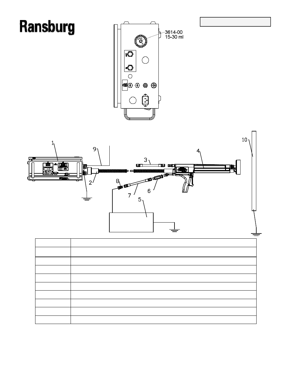
9060 Power Supply 80102
9060 Power Supply 80102
9060 Power Supply 80102
9060 Power Supply 80102----31X Connected to True Earth Ground
31X Connected to True Earth Ground
31X Connected to True Earth Ground
31X Connected to True Earth Ground
2
2
2
2
High Voltage Cable Connection to Power Supply
High Voltage Cable Connection to Power Supply
High Voltage Cable Connection to Power Supply
High Voltage Cable Connection to Power Supply
3
3
3
3
80089
80089
80089
80089----25 Air Hose Connected to Air Flow Switch “OUT”
25 Air Hose Connected to Air Flow Switch “OUT”
25 Air Hose Connected to Air Flow Switch “OUT”
25 Air Hose Connected to Air Flow Switch “OUT”
4
4
4
4
20987
20987
20987
20987----XX #2 Air Motor Applicator
XX #2 Air Motor Applicator
XX #2 Air Motor Applicator
XX #2 Air Motor Applicator
5
5
5
5
Earth grounded regulated paint supply
Earth grounded regulated paint supply
Earth grounded regulated paint supply
Earth grounded regulated paint supply
6
6
6
6
76938
76938
76938
76938----02 Inline Fluid Filter
02 Inline Fluid Filter
02 Inline Fluid Filter
02 Inline Fluid Filter
7
7
7
7
8340
8340
8340
8340----25 Fluid Hose
25 Fluid Hose
25 Fluid Hose
25 Fluid Hose
9
9
9
9
Regulated Air Source to Air Flow Switch “IN”
Regulated Air Source to Air Flow Switch “IN”
Regulated Air Source to Air Flow Switch “IN”
Regulated Air Source to Air Flow Switch “IN”
8
8
8
8
7244
7244
7244
7244----00 Adapter 9/16
00 Adapter 9/16
00 Adapter 9/16
00 Adapter 9/16----18 LH (M) to 3/8
18 LH (M) to 3/8
18 LH (M) to 3/8
18 LH (M) to 3/8----18 NPSM(F)
18 NPSM(F)
18 NPSM(F)
18 NPSM(F)
10
10
10
10
Earth Grounded Target
Earth Grounded Target
Earth Grounded Target
Earth Grounded Target
Figure 4: Equipment Installation Diagram
Figure 4: Equipment Installation Diagram
Figure 4: Equipment Installation Diagram
Figure 4: Equipment Installation Diagram
Figure 3: Di
Figure 3: Di
Figure 3: Di
Figure 3: Di----Electric Oil Installation
Electric Oil Installation
Electric Oil Installation
Electric Oil Installation
INSTALLATION
INSTALLATION
INSTALLATION
INSTALLATION