Air/fluid fitting installation pro, Air hose, Installation feed tube, bell – Ransburg No. 2 Air Motor Atex Approved Unit 80086-XX User Manual
Page 16
AH
AH
AH
AH----12
12
12
12----01.03 No. 2 Air Motor Handgun
01.03 No. 2 Air Motor Handgun
01.03 No. 2 Air Motor Handgun
01.03 No. 2 Air Motor Handgun
16
16
16
16
Ransburg supplies standard the 80089
Ransburg supplies standard the 80089
Ransburg supplies standard the 80089
Ransburg supplies standard the 80089----25
25
25
25
(7.6 m, 25 ft.) air hose and 8340
(7.6 m, 25 ft.) air hose and 8340
(7.6 m, 25 ft.) air hose and 8340
(7.6 m, 25 ft.) air hose and 8340----25 (7.6 m,
25 (7.6 m,
25 (7.6 m,
25 (7.6 m,
25 ft.) fluid hose standard with the 80086
25 ft.) fluid hose standard with the 80086
25 ft.) fluid hose standard with the 80086
25 ft.) fluid hose standard with the 80086----
XX unit. Other hose lengths up to 30.5 m
XX unit. Other hose lengths up to 30.5 m
XX unit. Other hose lengths up to 30.5 m
XX unit. Other hose lengths up to 30.5 m
(100 ft.) are also available as optional
(100 ft.) are also available as optional
(100 ft.) are also available as optional
(100 ft.) are also available as optional
lengths.
lengths.
lengths.
lengths.
NOTE
NOTE
NOTE
NOTE
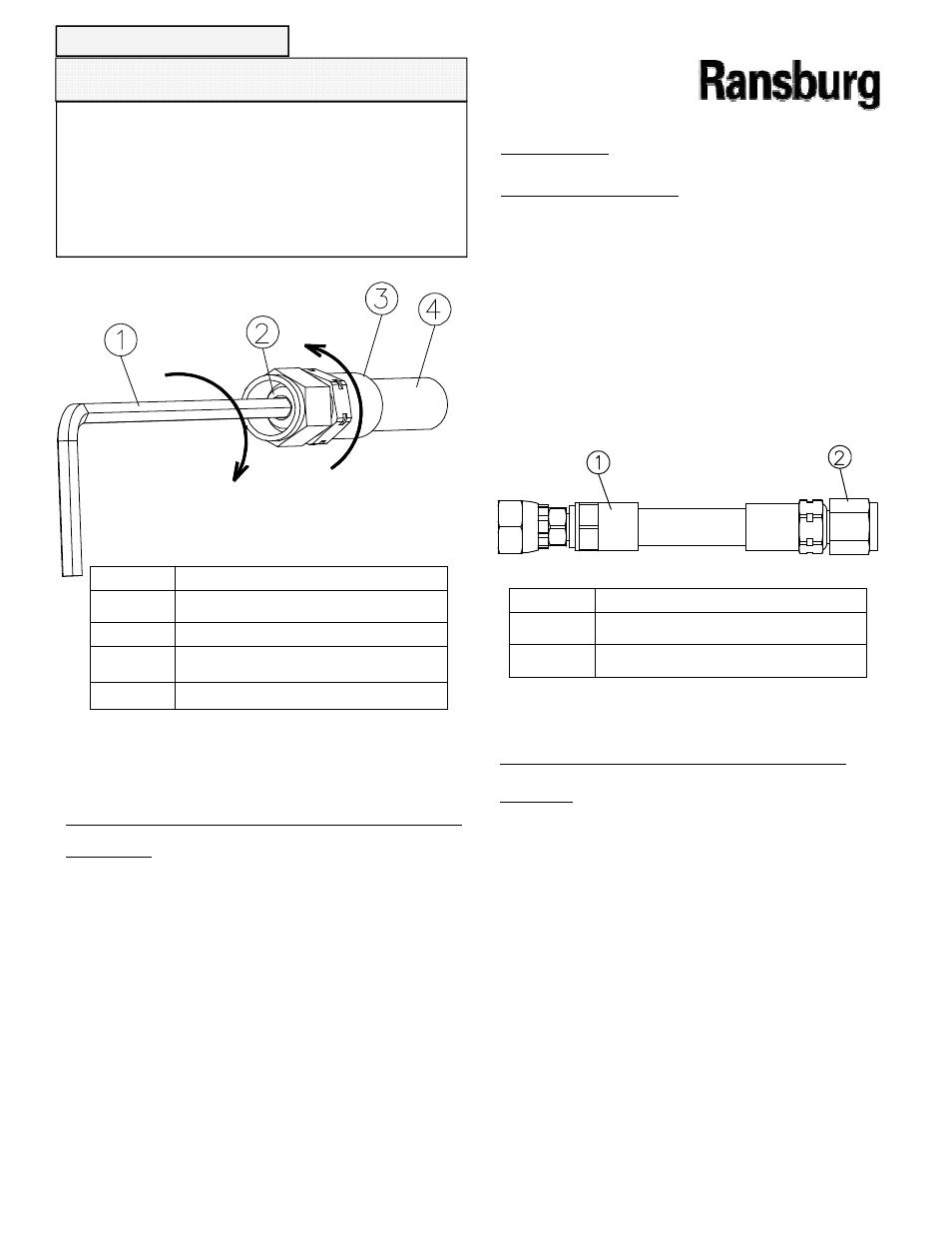
Air/Fluid Fitting Installation Pro-
Air/Fluid Fitting Installation Pro-
Air/Fluid Fitting Installation Pro-
Air/Fluid Fitting Installation Pro-
cedure
cedure
cedure
cedure
1. Lubricate all fittings with dielectric grease.
1. Lubricate all fittings with dielectric grease.
1. Lubricate all fittings with dielectric grease.
1. Lubricate all fittings with dielectric grease.
2. Screw ferrule (item 3) counterclockwise onto
2. Screw ferrule (item 3) counterclockwise onto
2. Screw ferrule (item 3) counterclockwise onto
2. Screw ferrule (item 3) counterclockwise onto
hose (item 4) until it bottoms, then back it off
hose (item 4) until it bottoms, then back it off
hose (item 4) until it bottoms, then back it off
hose (item 4) until it bottoms, then back it off
approximately 3.2 mm (1/8”).
approximately 3.2 mm (1/8”).
approximately 3.2 mm (1/8”).
approximately 3.2 mm (1/8”).
3. Install nut over union stem and start the stem
3. Install nut over union stem and start the stem
3. Install nut over union stem and start the stem
3. Install nut over union stem and start the stem
into the hose.
into the hose.
into the hose.
into the hose.
4. Using a 4.5 mm hex key (3/16
4. Using a 4.5 mm hex key (3/16
4. Using a 4.5 mm hex key (3/16
4. Using a 4.5 mm hex key (3/16----inch ), screw
inch ), screw
inch ), screw
inch ), screw
the union stem into the hose until it bottoms
the union stem into the hose until it bottoms
the union stem into the hose until it bottoms
the union stem into the hose until it bottoms
against the ferrule.
against the ferrule.
against the ferrule.
against the ferrule.
Item #
Item #
Item #
Item # Description
Description
Description
Description
1
1
1
1
4.5 mm (3/16”) Hex Key
4.5 mm (3/16”) Hex Key
4.5 mm (3/16”) Hex Key
4.5 mm (3/16”) Hex Key
2
2
2
2
Stem
Stem
Stem
Stem
3
3
3
3
Ferrule
Ferrule
Ferrule
Ferrule
4
4
4
4
Hose (Fluid or Air)
Hose (Fluid or Air)
Hose (Fluid or Air)
Hose (Fluid or Air)
Figure 5: Air or Fluid Fitting Assembly Procedure
Figure 5: Air or Fluid Fitting Assembly Procedure
Figure 5: Air or Fluid Fitting Assembly Procedure
Figure 5: Air or Fluid Fitting Assembly Procedure
Air Hose
Air Hose
Air Hose
Air Hose
(Refer to Figure 6)
(Refer to Figure 6)
(Refer to Figure 6)
(Refer to Figure 6)
1.
1.
1.
1. Connect the 9/16
Connect the 9/16
Connect the 9/16
Connect the 9/16----18 thread to the applica-
18 thread to the applica-
18 thread to the applica-
18 thread to the applica-
tor air inlet.
tor air inlet.
tor air inlet.
tor air inlet.
2.
2.
2.
2. Connect the 3/8 NPS(F) fitting to the “out”
Connect the 3/8 NPS(F) fitting to the “out”
Connect the 3/8 NPS(F) fitting to the “out”
Connect the 3/8 NPS(F) fitting to the “out”
port of the flow switch of the poser supply.
port of the flow switch of the poser supply.
port of the flow switch of the poser supply.
port of the flow switch of the poser supply.
Installation Feed Tube, Bell,
Installation Feed Tube, Bell,
Installation Feed Tube, Bell,
Installation Feed Tube, Bell,
Brush
Brush
Brush
Brush
1. Install the proper feed tube into the opening
1. Install the proper feed tube into the opening
1. Install the proper feed tube into the opening
1. Install the proper feed tube into the opening
in the applicator. See figure 7. Position the
in the applicator. See figure 7. Position the
in the applicator. See figure 7. Position the
in the applicator. See figure 7. Position the
tube at approximately as shown in the figure.
tube at approximately as shown in the figure.
tube at approximately as shown in the figure.
tube at approximately as shown in the figure.
2. Insert the 80084
2. Insert the 80084
2. Insert the 80084
2. Insert the 80084----00 brush into the barrel.
00 brush into the barrel.
00 brush into the barrel.
00 brush into the barrel.
Position it as shown in figure 7.
Position it as shown in figure 7.
Position it as shown in figure 7.
Position it as shown in figure 7.
Item #
Item #
Item #
Item # Description
Description
Description
Description
1
1
1
1
3/8 NPS(F)
3/8 NPS(F)
3/8 NPS(F)
3/8 NPS(F) ----To Flow Switch
To Flow Switch
To Flow Switch
To Flow Switch
2
2
2
2
9/16
9/16
9/16
9/16----18 to Applicator
18 to Applicator
18 to Applicator
18 to Applicator
Figure 6: Air Fitting Assembly Procedure
Figure 6: Air Fitting Assembly Procedure
Figure 6: Air Fitting Assembly Procedure
Figure 6: Air Fitting Assembly Procedure
INSTALLATION
INSTALLATION
INSTALLATION
INSTALLATION