No. 2 handgun brush, Refer to figure 10) – Ransburg No. 2 Air Motor Atex Approved Unit 80086-XX User Manual
Page 19
19
19
19
19
AH
AH
AH
AH----12
12
12
12----01.03 No. 2 Air Motor Handgun
01.03 No. 2 Air Motor Handgun
01.03 No. 2 Air Motor Handgun
01.03 No. 2 Air Motor Handgun
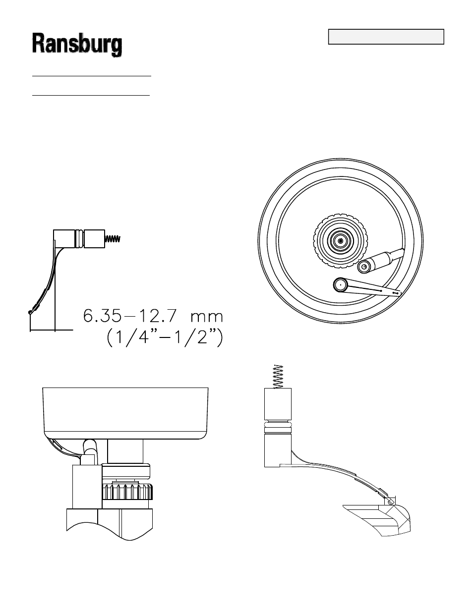
The brush should normally have a slight curve to the
The brush should normally have a slight curve to the
The brush should normally have a slight curve to the
The brush should normally have a slight curve to the
arm. The more pressure applied the lesser the
arm. The more pressure applied the lesser the
arm. The more pressure applied the lesser the
arm. The more pressure applied the lesser the
curve
curve
curve
curve
(see Figure 4). The tip of the brush
(see Figure 4). The tip of the brush
(see Figure 4). The tip of the brush
(see Figure 4). The tip of the brush
assembly must
assembly must
assembly must
assembly must
be inspected prior to each use for wear. When one
be inspected prior to each use for wear. When one
be inspected prior to each use for wear. When one
be inspected prior to each use for wear. When one----half
half
half
half
(1/2) of the plastic tip is worn away the brush assembly
(1/2) of the plastic tip is worn away the brush assembly
(1/2) of the plastic tip is worn away the brush assembly
(1/2) of the plastic tip is worn away the brush assembly
should be replaced (see Figure 10).
should be replaced (see Figure 10).
should be replaced (see Figure 10).
should be replaced (see Figure 10).
No. 2 Handgun Brush
No. 2 Handgun Brush
No. 2 Handgun Brush
No. 2 Handgun Brush
Positioning and Wear
Positioning and Wear
Positioning and Wear
Positioning and Wear
(Refer to Figure 10)
(Refer to Figure 10)
(Refer to Figure 10)
(Refer to Figure 10)
When installing the electrical contact brush (80085
When installing the electrical contact brush (80085
When installing the electrical contact brush (80085
When installing the electrical contact brush (80085----
00), it is important that it is properly positioned to pro-
00), it is important that it is properly positioned to pro-
00), it is important that it is properly positioned to pro-
00), it is important that it is properly positioned to pro-
vide LIGHT CONTACT with the bell conductive coat-
vide LIGHT CONTACT with the bell conductive coat-
vide LIGHT CONTACT with the bell conductive coat-
vide LIGHT CONTACT with the bell conductive coat-
ing. Excessive contact pressure from the contact
ing. Excessive contact pressure from the contact
ing. Excessive contact pressure from the contact
ing. Excessive contact pressure from the contact
brush will wear away the conductive coating or the
brush will wear away the conductive coating or the
brush will wear away the conductive coating or the
brush will wear away the conductive coating or the
brush tip, causing poor electrical contact. The small
brush tip, causing poor electrical contact. The small
brush tip, causing poor electrical contact. The small
brush tip, causing poor electrical contact. The small
plastic pad at the tip of the brush arm should lightly
plastic pad at the tip of the brush arm should lightly
plastic pad at the tip of the brush arm should lightly
plastic pad at the tip of the brush arm should lightly
contact the black bell coating, not the wire. The wire
contact the black bell coating, not the wire. The wire
contact the black bell coating, not the wire. The wire
contact the black bell coating, not the wire. The wire
should never contact the coating. The tip of the brush
should never contact the coating. The tip of the brush
should never contact the coating. The tip of the brush
should never contact the coating. The tip of the brush
should not extend past the edge of the bell cup or into
should not extend past the edge of the bell cup or into
should not extend past the edge of the bell cup or into
should not extend past the edge of the bell cup or into
the radius at the edge (see Figure 10).
the radius at the edge (see Figure 10).
the radius at the edge (see Figure 10).
the radius at the edge (see Figure 10).
Figure 10
Figure 10
Figure 10
Figure 10----1: Un
1: Un
1: Un
1: Un----Installed Brush Shape
Installed Brush Shape
Installed Brush Shape
Installed Brush Shape
Figure 10
Figure 10
Figure 10
Figure 10----2: Brush Contact Position
2: Brush Contact Position
2: Brush Contact Position
2: Brush Contact Position
Figure 10
Figure 10
Figure 10
Figure 10----3: Brush and Feed Tube Positioning
3: Brush and Feed Tube Positioning
3: Brush and Feed Tube Positioning
3: Brush and Feed Tube Positioning
Figure 10
Figure 10
Figure 10
Figure 10----4: Brush Contact Area
4: Brush Contact Area
4: Brush Contact Area
4: Brush Contact Area
INSTALLATION
INSTALLATION
INSTALLATION
INSTALLATION