Ransburg No. 2 Air Motor Atex Approved Unit 80086-XX User Manual
Page 17
17
17
17
17
AH
AH
AH
AH----12
12
12
12----01.03 No. 2 Air Motor Handgun
01.03 No. 2 Air Motor Handgun
01.03 No. 2 Air Motor Handgun
01.03 No. 2 Air Motor Handgun
Item #
Item #
Item #
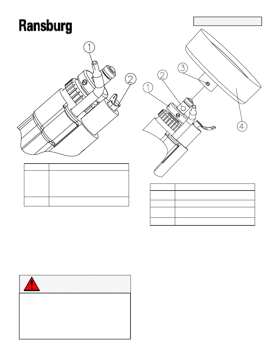
Item # Description
Description
Description
Description
1
1
1
1
Feed Tube 3700
Feed Tube 3700
Feed Tube 3700
Feed Tube 3700----00 for 4” Bell
00 for 4” Bell
00 for 4” Bell
00 for 4” Bell
Feed Tube 6335
Feed Tube 6335
Feed Tube 6335
Feed Tube 6335----00 for 2 3/4”
00 for 2 3/4”
00 for 2 3/4”
00 for 2 3/4”
Bell
Bell
Bell
Bell
2
2
2
2
80085
80085
80085
80085----00 Brush
00 Brush
00 Brush
00 Brush
Figure 7: Initial Position of Feed Tube and Brush
Figure 7: Initial Position of Feed Tube and Brush
Figure 7: Initial Position of Feed Tube and Brush
Figure 7: Initial Position of Feed Tube and Brush
3.
3.
3.
3. Install the bell over the shaft. Hold the shaft
Install the bell over the shaft. Hold the shaft
Install the bell over the shaft. Hold the shaft
Install the bell over the shaft. Hold the shaft
of the applicator and rotate the bell onto the
of the applicator and rotate the bell onto the
of the applicator and rotate the bell onto the
of the applicator and rotate the bell onto the
shaft until the bell is completely seated. Align
shaft until the bell is completely seated. Align
shaft until the bell is completely seated. Align
shaft until the bell is completely seated. Align
the set screw and the flat on the shaft. Tighten
the set screw and the flat on the shaft. Tighten
the set screw and the flat on the shaft. Tighten
the set screw and the flat on the shaft. Tighten
the set screw at the bell hub hand tight. (Refer
the set screw at the bell hub hand tight. (Refer
the set screw at the bell hub hand tight. (Refer
the set screw at the bell hub hand tight. (Refer
to Figure 8)
to Figure 8)
to Figure 8)
to Figure 8)
W A R N I N G
W A R N I N G
W A R N I N G
W A R N I N G
Replacing the plastic set screw with one
Replacing the plastic set screw with one
Replacing the plastic set screw with one
Replacing the plastic set screw with one of
of
of
of
conductive material (metal) will cause a
conductive material (metal) will cause a
conductive material (metal) will cause a
conductive material (metal) will cause a
hazardous condition to exist, capable of
hazardous condition to exist, capable of
hazardous condition to exist, capable of
hazardous condition to exist, capable of
producing an electrical discharge possible
producing an electrical discharge possible
producing an electrical discharge possible
producing an electrical discharge possible
of sparking a fire. In all cases use the plas-
of sparking a fire. In all cases use the plas-
of sparking a fire. In all cases use the plas-
of sparking a fire. In all cases use the plas-
tic screw provided or provided as a spare
tic screw provided or provided as a spare
tic screw provided or provided as a spare
tic screw provided or provided as a spare
part.
part.
part.
part.
Item #
Item #
Item #
Item # Description
Description
Description
Description
1
1
1
1
No. 2 Motor Shaft
No. 2 Motor Shaft
No. 2 Motor Shaft
No. 2 Motor Shaft
2
2
2
2
Shaft Locating Flat
Shaft Locating Flat
Shaft Locating Flat
Shaft Locating Flat
3
3
3
3
Bell Set Screw
Bell Set Screw
Bell Set Screw
Bell Set Screw
4
4
4
4
Bell
Bell
Bell
Bell
Figure 8: Installing Bell on Shaft
Figure 8: Installing Bell on Shaft
Figure 8: Installing Bell on Shaft
Figure 8: Installing Bell on Shaft
4.
4.
4.
4. Re
Re
Re
Re----position the feed tube in the bell cavity
position the feed tube in the bell cavity
position the feed tube in the bell cavity
position the feed tube in the bell cavity
at approximately the 4 to 5 o’clock position.
at approximately the 4 to 5 o’clock position.
at approximately the 4 to 5 o’clock position.
at approximately the 4 to 5 o’clock position.
The feed tube should NOT rub on the bell. Ad-
The feed tube should NOT rub on the bell. Ad-
The feed tube should NOT rub on the bell. Ad-
The feed tube should NOT rub on the bell. Ad-
just the feed tube if necessary, by rotating it or
just the feed tube if necessary, by rotating it or
just the feed tube if necessary, by rotating it or
just the feed tube if necessary, by rotating it or
sliding it forward or backward in the barrel.
sliding it forward or backward in the barrel.
sliding it forward or backward in the barrel.
sliding it forward or backward in the barrel.
INSTALLATION
INSTALLATION
INSTALLATION
INSTALLATION