Cable/ air motor – Ransburg No. 2 Air Motor Atex Approved Unit 80086-XX User Manual
Page 34
AH
AH
AH
AH----12
12
12
12----01.03 No. 2 Air Motor Handgun
01.03 No. 2 Air Motor Handgun
01.03 No. 2 Air Motor Handgun
01.03 No. 2 Air Motor Handgun
34
34
34
34
CABLE/ AIR MOTOR
CABLE/ AIR MOTOR
CABLE/ AIR MOTOR
CABLE/ AIR MOTOR
ASSEMBLY
ASSEMBLY
ASSEMBLY
ASSEMBLY
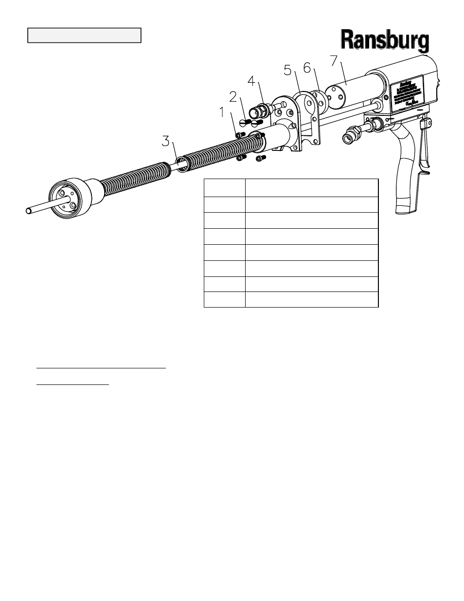
1. Remove the (4) socket head screws from
1. Remove the (4) socket head screws from
1. Remove the (4) socket head screws from
1. Remove the (4) socket head screws from
the rear of the applicator using a 9/64” hex
the rear of the applicator using a 9/64” hex
the rear of the applicator using a 9/64” hex
the rear of the applicator using a 9/64” hex
key wrench.
key wrench.
key wrench.
key wrench.
2. Remove the two slot headed screws from
2. Remove the two slot headed screws from
2. Remove the two slot headed screws from
2. Remove the two slot headed screws from
the assembly.
the assembly.
the assembly.
the assembly.
3. Remove the air inlet slide valve assembly
3. Remove the air inlet slide valve assembly
3. Remove the air inlet slide valve assembly
3. Remove the air inlet slide valve assembly
by turning the hex on the assembly in a coun-
by turning the hex on the assembly in a coun-
by turning the hex on the assembly in a coun-
by turning the hex on the assembly in a coun-
ter clockwise direction.
ter clockwise direction.
ter clockwise direction.
ter clockwise direction.
4. Pull the high voltage cable assembly
4. Pull the high voltage cable assembly
4. Pull the high voltage cable assembly
4. Pull the high voltage cable assembly
straight out of the assembly. The spacer, the
straight out of the assembly. The spacer, the
straight out of the assembly. The spacer, the
straight out of the assembly. The spacer, the
gasket and the air motor will also pull out of
gasket and the air motor will also pull out of
gasket and the air motor will also pull out of
gasket and the air motor will also pull out of
the barrel.
the barrel.
the barrel.
the barrel.
Figure 19: High Voltage Cable and Air Motor Removal Diagram
Figure 19: High Voltage Cable and Air Motor Removal Diagram
Figure 19: High Voltage Cable and Air Motor Removal Diagram
Figure 19: High Voltage Cable and Air Motor Removal Diagram
Item #
Item #
Item #
Item # Description
Description
Description
Description
1
1
1
1
(4) Socket Head Screws
(4) Socket Head Screws
(4) Socket Head Screws
(4) Socket Head Screws
2
2
2
2
(2) Slotted Head Screws
(2) Slotted Head Screws
(2) Slotted Head Screws
(2) Slotted Head Screws
3
3
3
3
High Voltage Cable Assembly
High Voltage Cable Assembly
High Voltage Cable Assembly
High Voltage Cable Assembly
4
4
4
4
Air Inlet Slide Valve Assembly
Air Inlet Slide Valve Assembly
Air Inlet Slide Valve Assembly
Air Inlet Slide Valve Assembly
5
5
5
5
Gasket
Gasket
Gasket
Gasket
6
6
6
6
Spacer
Spacer
Spacer
Spacer
7
7
7
7
Air Motor Assembly
Air Motor Assembly
Air Motor Assembly
Air Motor Assembly
5. Inspect gasket for any damage. Replace if
5. Inspect gasket for any damage. Replace if
5. Inspect gasket for any damage. Replace if
5. Inspect gasket for any damage. Replace if
required.
required.
required.
required.
6. Check the applicator end of the cable assem-
6. Check the applicator end of the cable assem-
6. Check the applicator end of the cable assem-
6. Check the applicator end of the cable assem-
bly to ensure the spring is attached to the cable.
bly to ensure the spring is attached to the cable.
bly to ensure the spring is attached to the cable.
bly to ensure the spring is attached to the cable.
Apply a generous coating of di
Apply a generous coating of di
Apply a generous coating of di
Apply a generous coating of di----electric lubricant
electric lubricant
electric lubricant
electric lubricant
(LSCH0009
(LSCH0009
(LSCH0009
(LSCH0009----00) to the applicator end of the
00) to the applicator end of the
00) to the applicator end of the
00) to the applicator end of the
high voltage cable.
high voltage cable.
high voltage cable.
high voltage cable.
7. Attach the motor to the cable assembly using
7. Attach the motor to the cable assembly using
7. Attach the motor to the cable assembly using
7. Attach the motor to the cable assembly using
the (2) slotted screws and the air inlet slide
the (2) slotted screws and the air inlet slide
the (2) slotted screws and the air inlet slide
the (2) slotted screws and the air inlet slide
valve assembly
valve assembly
valve assembly
valve assembly
8. Slide the entire assembly into the barrel in-
8. Slide the entire assembly into the barrel in-
8. Slide the entire assembly into the barrel in-
8. Slide the entire assembly into the barrel in-
suring the cable end and all other parts are
suring the cable end and all other parts are
suring the cable end and all other parts are
suring the cable end and all other parts are
properly positioned. Insert the (4) socket head
properly positioned. Insert the (4) socket head
properly positioned. Insert the (4) socket head
properly positioned. Insert the (4) socket head
screws and tighten only by hand.
screws and tighten only by hand.
screws and tighten only by hand.
screws and tighten only by hand.
MAINTENANCE
MAINTENANCE
MAINTENANCE
MAINTENANCE