Motor assembly replacement, Handle assembly – Ransburg No. 2 Air Motor Atex Approved Unit 80086-XX User Manual
Page 35
35
35
35
35
AH
AH
AH
AH----12
12
12
12----01.03 No. 2 Air Motor Handgun
01.03 No. 2 Air Motor Handgun
01.03 No. 2 Air Motor Handgun
01.03 No. 2 Air Motor Handgun
Ensure the power is “OFF” to the 9050 power
Ensure the power is “OFF” to the 9050 power
Ensure the power is “OFF” to the 9050 power
Ensure the power is “OFF” to the 9050 power
supply prior to rotating the bell in step 9.
supply prior to rotating the bell in step 9.
supply prior to rotating the bell in step 9.
supply prior to rotating the bell in step 9.
W A R N I N G
W A R N I N G
W A R N I N G
W A R N I N G
9. Mount the applicator in a padded vise and
9. Mount the applicator in a padded vise and
9. Mount the applicator in a padded vise and
9. Mount the applicator in a padded vise and
turn the motor on by sliding the air inlet slide
turn the motor on by sliding the air inlet slide
turn the motor on by sliding the air inlet slide
turn the motor on by sliding the air inlet slide
valve forward. Listen to the audible pitch of the
valve forward. Listen to the audible pitch of the
valve forward. Listen to the audible pitch of the
valve forward. Listen to the audible pitch of the
motor.
motor.
motor.
motor.
10. Alternately tighten (4) socket head screws
10. Alternately tighten (4) socket head screws
10. Alternately tighten (4) socket head screws
10. Alternately tighten (4) socket head screws
until snug. If motor shaft begins to slow (audible
until snug. If motor shaft begins to slow (audible
until snug. If motor shaft begins to slow (audible
until snug. If motor shaft begins to slow (audible
pitch changes), loosen screws slightly to relieve
pitch changes), loosen screws slightly to relieve
pitch changes), loosen screws slightly to relieve
pitch changes), loosen screws slightly to relieve
binding. DO NOT over tighten screws so that
binding. DO NOT over tighten screws so that
binding. DO NOT over tighten screws so that
binding. DO NOT over tighten screws so that
gasket is squeezed outward beyond the outer
gasket is squeezed outward beyond the outer
gasket is squeezed outward beyond the outer
gasket is squeezed outward beyond the outer
dimension of the barrel.
dimension of the barrel.
dimension of the barrel.
dimension of the barrel.
Over tightening of the (4) socket head
Over tightening of the (4) socket head
Over tightening of the (4) socket head
Over tightening of the (4) socket head
screws can break threaded inserts out of
screws can break threaded inserts out of
screws can break threaded inserts out of
screws can break threaded inserts out of
plastic barrel.
plastic barrel.
plastic barrel.
plastic barrel.
C A U T I O N
C A U T I O N
C A U T I O N
C A U T I O N
Motor Assembly Replacement
Motor Assembly Replacement
Motor Assembly Replacement
Motor Assembly Replacement
1. Follow instructions for removing the cable as-
1. Follow instructions for removing the cable as-
1. Follow instructions for removing the cable as-
1. Follow instructions for removing the cable as-
sembly and motor assembly from the barrel (see
sembly and motor assembly from the barrel (see
sembly and motor assembly from the barrel (see
sembly and motor assembly from the barrel (see
"Cable Assembly Replacement" in the
"Cable Assembly Replacement" in the
"Cable Assembly Replacement" in the
"Cable Assembly Replacement" in the
"Maintenance" section).
"Maintenance" section).
"Maintenance" section).
"Maintenance" section).
2. Replace the motor as required.
2. Replace the motor as required.
2. Replace the motor as required.
2. Replace the motor as required.
3. Follow the assembly instructions for replac-
3. Follow the assembly instructions for replac-
3. Follow the assembly instructions for replac-
3. Follow the assembly instructions for replac-
ing the high voltage cable (see "Cable Assem-
ing the high voltage cable (see "Cable Assem-
ing the high voltage cable (see "Cable Assem-
ing the high voltage cable (see "Cable Assem-
bly Replacement" in the "Maintenance" section).
bly Replacement" in the "Maintenance" section).
bly Replacement" in the "Maintenance" section).
bly Replacement" in the "Maintenance" section).
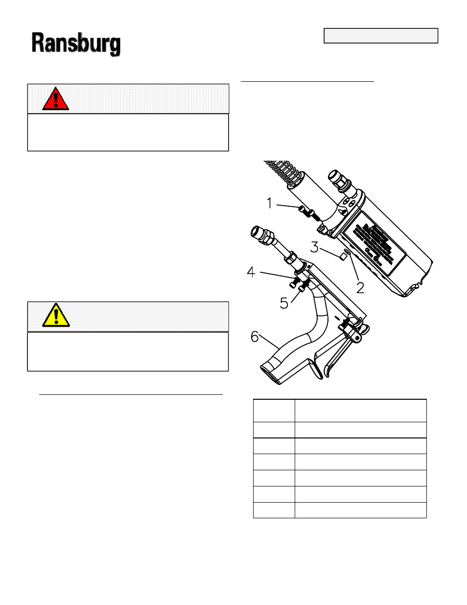
HANDLE ASSEMBLY
HANDLE ASSEMBLY
HANDLE ASSEMBLY
HANDLE ASSEMBLY
1. Invert the applicator and remove the (4)
1. Invert the applicator and remove the (4)
1. Invert the applicator and remove the (4)
1. Invert the applicator and remove the (4)
socket head cap screws and lock washers
socket head cap screws and lock washers
socket head cap screws and lock washers
socket head cap screws and lock washers
from the underside of the handle assembly with
from the underside of the handle assembly with
from the underside of the handle assembly with
from the underside of the handle assembly with
a 9/64
a 9/64
a 9/64
a 9/64----inch hex key wrench. Refer to Figure 20.
inch hex key wrench. Refer to Figure 20.
inch hex key wrench. Refer to Figure 20.
inch hex key wrench. Refer to Figure 20.
Item #
Item #
Item #
Item # Description
Description
Description
Description
1
1
1
1
(2) Socket Head Screws
(2) Socket Head Screws
(2) Socket Head Screws
(2) Socket Head Screws
2
2
2
2
O
O
O
O----Ring
Ring
Ring
Ring
3
3
3
3
Bushing, Paint
Bushing, Paint
Bushing, Paint
Bushing, Paint
4
4
4
4
(4) Lock Washers
(4) Lock Washers
(4) Lock Washers
(4) Lock Washers
5
5
5
5
(2) Socket Head Screws
(2) Socket Head Screws
(2) Socket Head Screws
(2) Socket Head Screws
6
6
6
6
Handle Assembly
Handle Assembly
Handle Assembly
Handle Assembly
Figure 20: Handle Assembly Removal
Figure 20: Handle Assembly Removal
Figure 20: Handle Assembly Removal
Figure 20: Handle Assembly Removal
MAINTENANCE
MAINTENANCE
MAINTENANCE
MAINTENANCE