Electric test, Electric test in section 9.1.3.2, Conjunction with optic test, see section 9.1.3.2 – Teledyne 6200A - Sulfides analyzer User Manual
Page 159
TAI Model 6200A SO
2
Analyzer Operator Manual, 02164, Rev. G
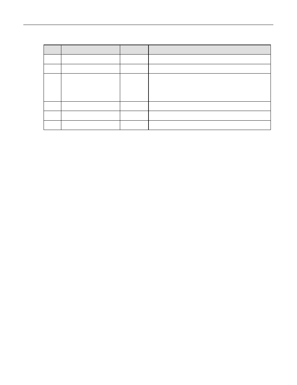
Table 9-4: Diagnostic Mode - Signal I/O (Continued)
No
Signal
Control
Description
34
DAC_CHAN_2
NO
Output of spare (DAC2) channel in mV.
35
DAC_CHAN_3
NO
Test Channel (DAC3) output.
36
UVLAMP_SIGNAL
NO
Current UV lamp signal voltage in mV. Same as UV
LAMP in TEST menu. Bi-polar, typically 0-5000 mV
range. A constant value of 5000 mV indicates
offscale.
37 CONC_OUT_1
YES
DAC0
(SO
2
/RANGE1) analog output in mV
38 CONC_OUT_2
YES
DAC1
(SO
2
/RANGE2) analog output in mV
39
TEST_OUTPUT
YES
DAC3 (TEST CHANNEL) analog output in mV
9.1.3.2 Electric Test
This function injects a constant voltage between the preamplifier and the buffer amplifier on the
preamp board. Electric test checks part of the preamp, the V/F and computer for proper functioning.
The result of electric test should be a smooth quiet signal as shown by constant values for the SO
2
concentration. Likewise the analog outputs should produce a smooth quiet trace on a strip chart
(analog output range is set to 2000ppb and auto-ranging is disabled).
Procedure:
1. Scroll the TEST function to PMT.
2. Press SETUP-MORE-DIAG, scroll to ELECT TEST by pressing the NEXT button. When
ET appears, press ENTR to turn it on.
3. The value in PMT should come up to 2000 mV ± 1000mV in less than 15 sec.
If the HVPS or the span gain adjust on the preamp card has been changed without doing a
FACTORY CALIBRATE the reading in step 3 may be different than 2000 mV, since the overall
calibration affects ELECTRIC TEST. See Section 9.1.6 for factory calibration procedure.
4. To turn off ET press EXIT
If ET is a steady 2000 ± 1000 mV, that means the Power Supply Module, preamp buffer amplifier,
V/F, CPU, and display are all working properly.
9-16