Calibration quality, 10 c, Alibration – Teledyne 6200A - Sulfides analyzer User Manual
Page 132: Uality, Able, 16: c, Heck, Procedure section 7.10, Refer to table 7-16), 10 calibration quality
TAI Model 6200A SO
2
Analyzer Operator Manual, 02164, Rev. G
6200A with IZS option can be used to calibrate zero/span of one Range #, but not both. Other Range
# should be calibrated using external zero/span gas through sample port. Pressing CALZ (for zero)
or CALS (for span) keys will lead to show #1 and #2 the same way as CAL key except CALZ is
dedicated for zero air calibration while CALS is dedicated for span gas calibration. Zero/span valve
option is also treated same as IZS option except external zero/span gas are used for both Range#.
7.10 Calibration Quality
After Zero/Span is complete, it is very important to check the QUALITY of the calibration. The
calibration of the 6200A involves balancing several sections of electronics and software to
achieve an optimum balance of accuracy, noise, linearity and dynamic range.
The following procedure compares the Slope and Offset parameters in the equation used to
compute the SO
2
concentration. For an explanation of the use of these terms in the concentration
calculation see Section 5.2.2.5.
The slope and offset parameters are similar to the span and zero pots on an analog instrument.
Just as in the analog instrument, if the slope or offset get outside of a certain range, the
instrument will not perform as well.
The offset value gives information about the background signal level. Check the observed offset
value against the factory value in Table 2-1. If significantly higher check Section 9.1.6.
Increasing readings are a predictor of problems.
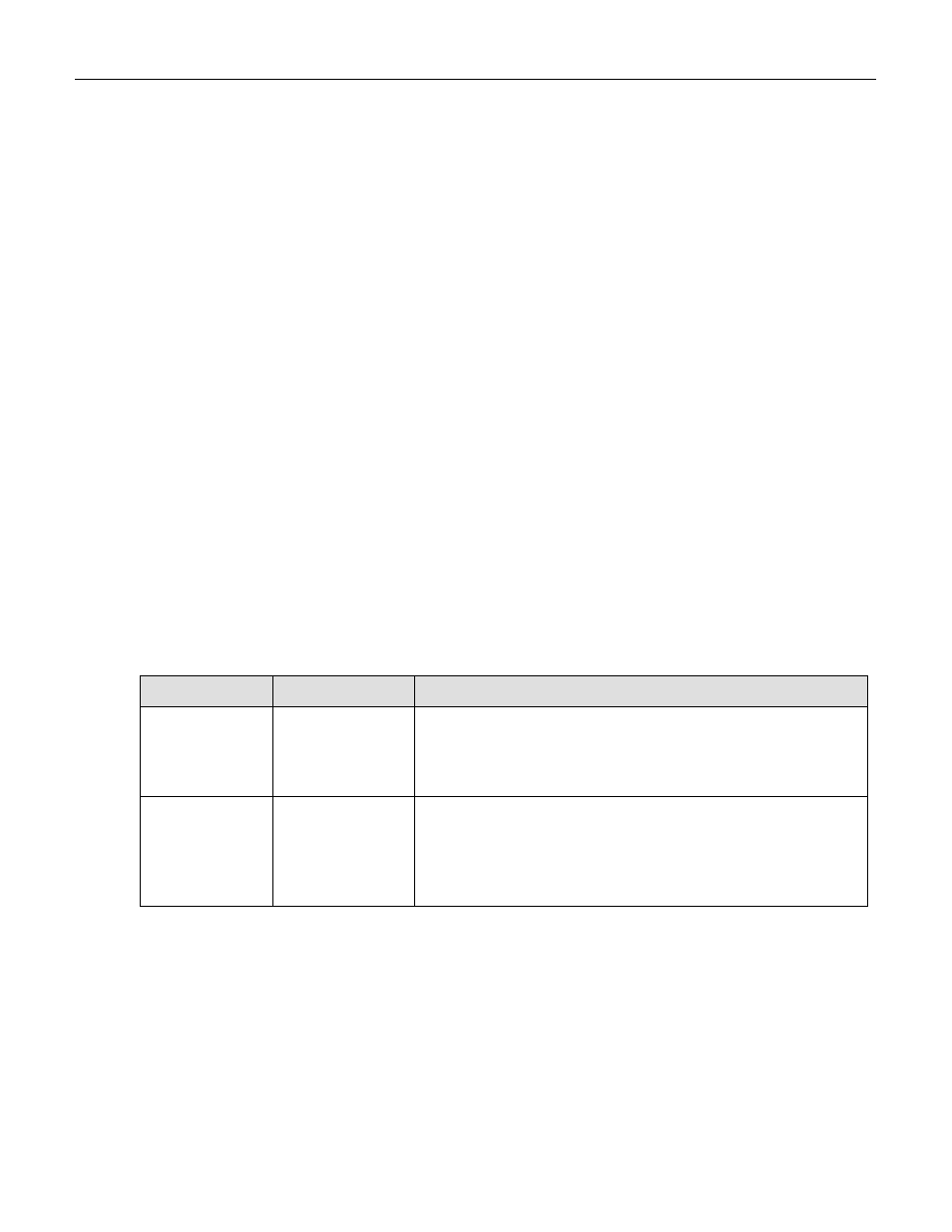
Table 7-16: Calibration Quality Check
Step Number
Action
Comment
1.
Scroll the TEST
function menu
until the SLOPE
is displayed.
Typical SLOPE value for SO
2
is 1.0
± 0.3. If the value is not
in this range, check Section 9.1.6. If the SLOPE value is in the
acceptable range the instrument will perform optimally.
2.
Scroll the TEST
function menu
until the
OFFSET is
displayed.
Typical number is between 50mV and 250mV which is mainly
the optical system background. If the OFFSET value is outside
this range, check Section 9.1.6.
After the above procedure is complete, the 6200A is ready to measure sample gas.
7-25