Able, 3: s, Ummary of – Teledyne 6200A - Sulfides analyzer User Manual
Page 155: Iagnostic, Odes
TAI Model 6200A SO
2
Analyzer Operator Manual, 02164, Rev. G
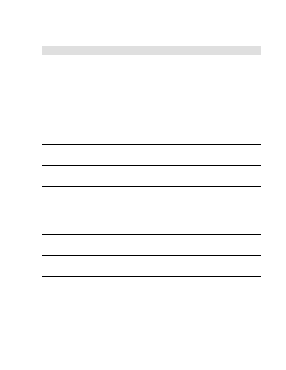
Table 9-3: Summary of Diagnostic Modes
DIAG Mode
Description
SIGNAL I/O
Gives access to the digital and analog inputs and outputs on the
V/F board. The status or value of all of the signals can be seen.
Some of the signals can be controlled from the keyboard. Table 9-
4 gives details on each signal and information on control
capabilities. NOTE - some signals can be toggled into states that
indicate warnings or other faults. These settings will remain in
effect until DIAG mode is exited, then the 6200A will resume
control over the signals.
ANALOG OUTPUT
Causes a test signal to be written to the analog output DAC's. The
signal consists of a scrolling 0%, 20%, 40%, 60%, 80%, 100% of
the analog output value. The scrolling may be stopped by
pressing the key underneath the % display to hold that value. The
exact voltage values depend on the jumper settings on the analog
output buffer amplifiers.
DAC CALIBRATION
The analog output is created by 4 digital-to-analog converters.
This selection starts a procedure to calibrate these outputs. Refer
to Section 9.3.3.1 for a detailed procedure.
OPTICAL TEST
Sets the 6200A into a known state and turns on an LED near the
PMT to test the instrument signal path. See Section 9.1.3.3 for
details on using this test.
ELECTRICAL TEST
Tests just the electronic portion of the PMT signal path. Used in
conjunction with optic test, see Section 9.1.3.2.
LAMP CAIBRATION
This feature allows to update the Lamp Calibration value.
Displayed value is the current lamp intensity and pressing ENTR
key will update the Lamp Calibration value. Refer to Section
9.4.2 for UV Lamp adjustment. See also Section 9.1.6 Factory
Calibration Procedure.
TEST CHANNEL OUTPUT
This feature allows to output scaled voltage of most test
measurement through the analog output terminal. Refer to Section
9.1.5.
RS-232
Causes a 1 second burst of data to be transmitted from the RS-232
port. Used to diagnose RS-232 port problems. See Section
9.1.3.6, 9.3.2 for RS-232 port diagnostic techniques.
9-12