1 analog input modules – Micromod Micro-DCI: 53MC5000 Multi-Loop Process Controller Installation User Manual
Page 53
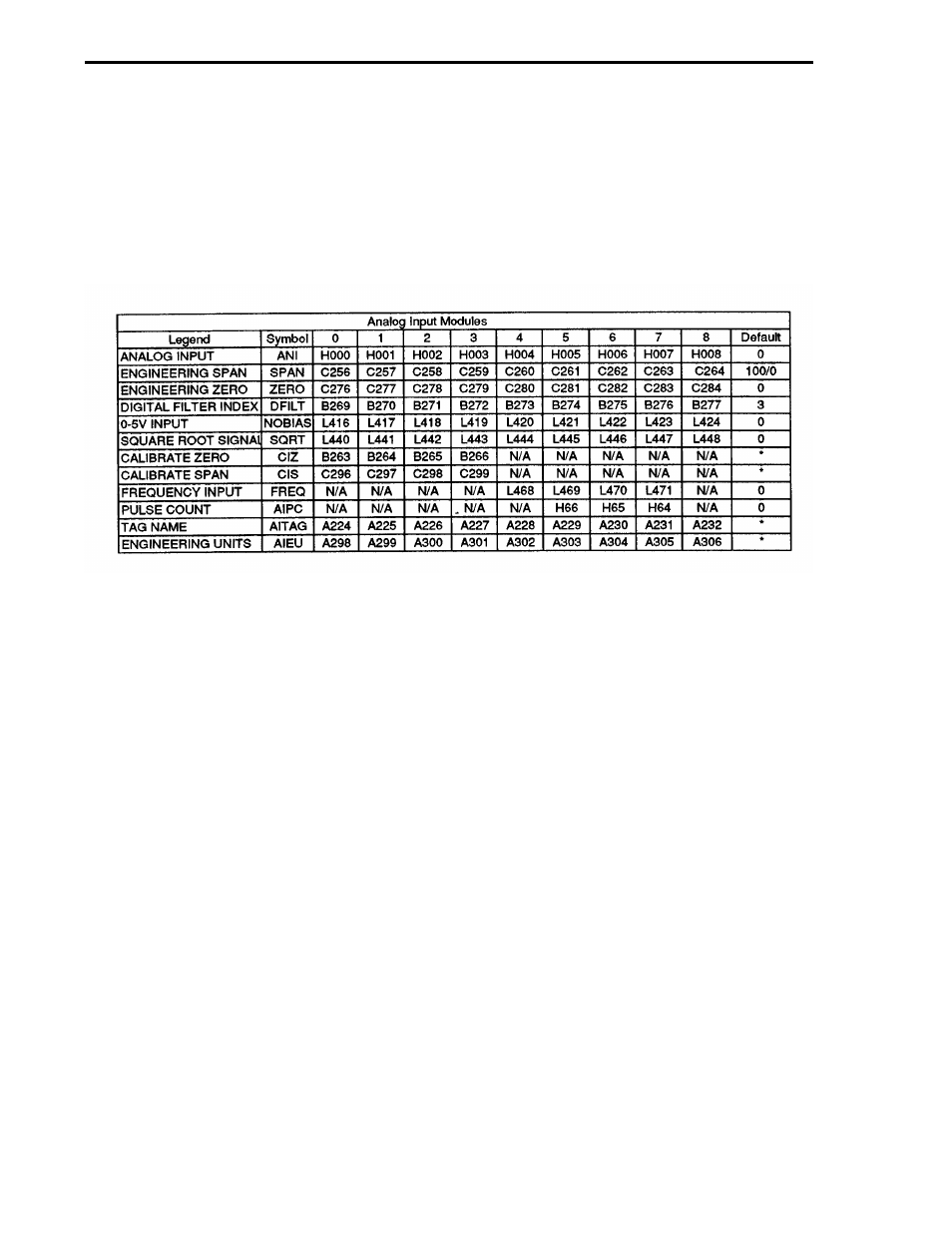
3.4.1 ANALOG INPUT MODULES
The analog input modules permit the user to configure the characteristics of each input. The avail-
able parameters are shown below. Inputs AI4 through AI8 are only active if the appropriate hard-
ware option is installed.
Each of the analog signals has its own set of parameters. To identify the data point corresponding
to each parameter refer to the following table.
0 - 5 INPUT VOLTAGE RANGE:
Input transmitter ranges of 0-5 or 1-5 volts are supported as standard analog inputs. Setting this pa-
rameter to "1" indicates the input ranges from 0 to 5 volts; setting it to "0" indicates a 1 to 5 volt
range.
SQUARE ROOT SIGNAL:
This parameter indicates whether the analog input signal should be interpreted as either a linear or
square root representation of the value. When square root is selected input signals less then about
1% (10% input range) force the input to its zero value. A "1" indicates square root while a "0" indi-
cates linear.
ENGINEERING SPAN and ZERO:
These parameters define the range of values that the analog input represents in engineering units.
Engineering Zero is the minimum range value. Maximum range value equals Engineering Zero plus
Engineering Span.
CALIBRATION ZERO and SPAN:
These parameters are set at the factory for correct operation of the associated input. They should
not need adjustment under normal operation.
MODULAR CONTROLLER QUICK START
3-28