Micromod Micro-DCI: 53MC5000 Multi-Loop Process Controller Installation User Manual
Page 35
3.2.3 DISPLAYING A MODULE
Refer to Section 3.11 for Keypad function in Module Mode
The navigational sequence would be the following
(Refer to Table 3-5):
•
Select Module Type (then Module, if there’s more than
one Module)
•
Select Page (Skipped when there’s only a single page)
•
Select Parameter
3.2.3.1 Procedure to Display a Module
•
Press the Mode button to enter the ENGINEER
mode indicated by the appearance of either CONFIG-
URE, DISPLAY or PROGRAM at the bottom of the
display.
•
If DISPLAY does not appear, press F2 until DISPLAY
appears
•
When DISPLAY is shown at the bottom, press F3.
•
Press F2 until MODULE appears at the bottom of the
display.
•
Press F3 to enter MODULE mode.
•
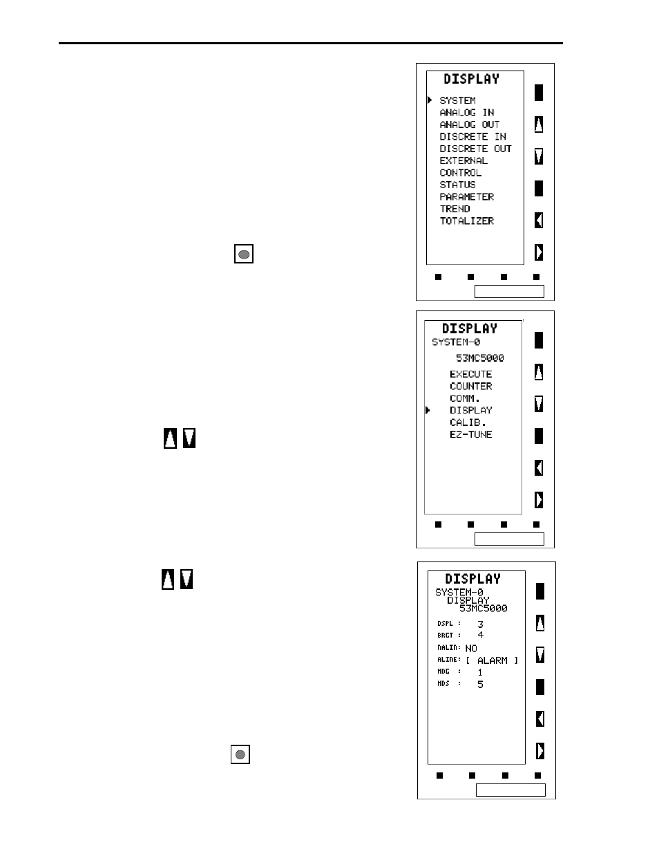
Press the button, if required, until the pointer
aligns with SYSTEM.
•
The screen should now appear as shown at the top
right.
•
Press F3 to enter the SYSTEM module.
•
The list of SYSTEM module pages now appear.
•
Press the button to scroll to the DISPLAY page.
•
The display should now appear as shown in the right
center screen.
•
Press F3 and the DISPLAY page parameters are
shown as the screen to the right shows.
•
The parameter BRGT, associated with Datapoint B012
storage location (refer to Section 3.2.2) is displayed as
the second entry in the list of parameters as shown in
screen to the right.
•
Press the Mode button to return the instrument to
operator mode.
MODULAR CONTROLLER QUICK START
3-10