Da t a gnd v+ shld – GF Signet 2551 Magmeter Flow Sensor - Display User Manual
Page 6
6
2551 Magmeter
-
+
12-24 V
10 W
12-24 V
10 W
4-20
mA
Total
reset
AUX
output
PLS
output
1
2
Gnd
-
+
+
+
Gnd
Freq. IN
Sen. Pwr
.
Freq. IN
Iso. Gnd
Std. Sensor
Open Collector
Sensor
1
2
3
4
Frequency Out
2551 Magmeter
24 VDC
Relay 1
Relay 2
NO1
NO2
NO3
NC1
NC2
NC3
C1
C2
C3
Relay 3
V+
5-24 VDC
Ground
Ground
Aux Pwr
Signet 5600
Auxiliary Power for:
Display backlighting
Relay Coils
V-
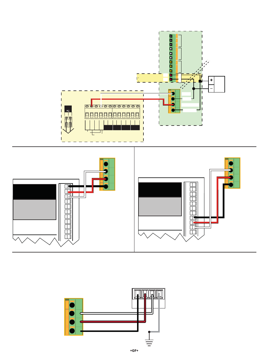
2551 Frequency Out to 8900 Controller:
2551 Digital (S
3
L) Out to 8900 Controller:
2551 Frequency or Digital (S
3
L) Out to 9900 Transmitter:
2551 Frequency Out to Signet 5600
5.4 Wiring to Signet Flow Instruments
The 2551-21 and -41 Magmeter can be con¿ gured in the OPTIONS menu to provide a Frequency or Digital (S
3
L) output.
Frequency output can be used by Signet 5600 Flow Transmitter, and by Signet 8900 Multi-Parameter Controller and 9900 Transmitter.
The Digital (S
3
L) output can be used by the 8900 and 9900.
3-8900.621C
I/O Module 3-8900.401-X
1
2
3
4
5
6
7
8
9
10
11
+5VDC (Black)
Freq. Input (Red)
GND (Shield)
+5VDC (Black)
Freq. Input 2 (Red)
S L (Red)
GND (White/Shield)
+5VDC (Black)
S L (Red)
GND (White/Shield)
3
3
Frequency
Input
1
Frequency
Input 2
OR
S3L
Input
2
S3L
Input
1
1
2
3
4
Ground
+5 VDC
Not used
Data
2551 Magmeter
1
2
3
4
DA
T
A
GND
V+
SHLD
2551 Magmeter
9900 Transmitter
+5 VDC
Ground
Not used
Frequency or S
3
L
3-8900.621C
I/O Module 3-8900.401-X
1
2
3
4
5
6
7
8
9
10
11
+5VDC (Black)
Freq. Input (Red)
GND (Shield)
+5VDC (Black)
Freq. Input 2 (Red)
S L (Red)
GND (White/Shield)
+5VDC (Black)
S L (Red)
GND (White/Shield)
3
3
Frequency
Input
1
Frequency
Input 2
OR
S3L
Input
2
S3L
Input
1
1
2
3
4
Ground
+5 VDC
Not used
Data
2551 Magmeter