Wiring, 6 to 26.4 vdc, 1 basic wiring – GF Signet 2551 Magmeter Flow Sensor - Display User Manual
Page 5
5
2551 Magmeter
5. Wiring
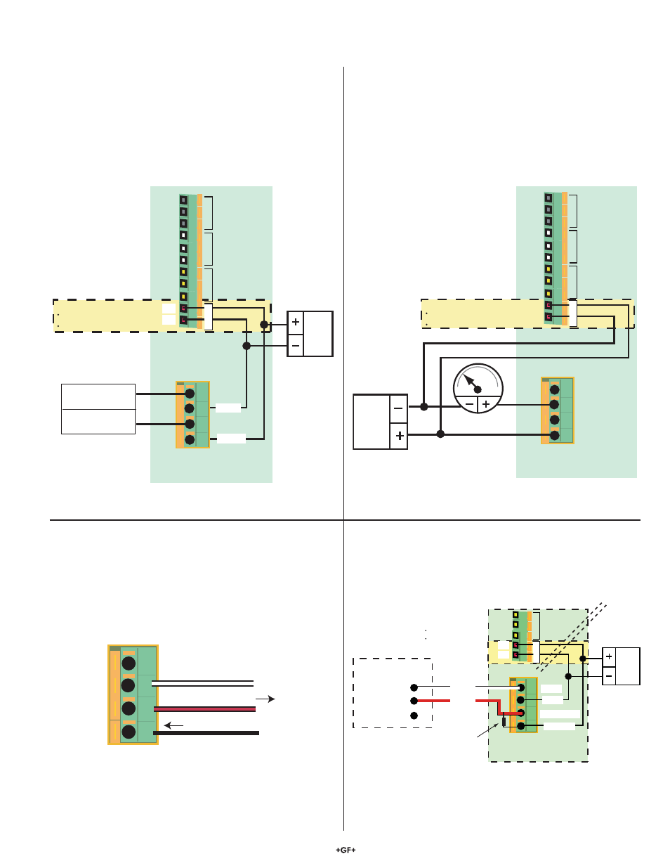
5.1 Basic
Wiring
2551 Magmeter
4.5-26.4
VDC
Relay 1
Relay 2
NO1
NO2
NO3
NC1
NC2
NC3
C1
C2
C3
Relay 3
V+
V-
+ VDC
- VDC
Aux Pwr
3
Frequency Out
Frequency ÷ 10 Out
(5 to 26.4 VDC)
**********************
Digital (S L) Out
(4.5 to 6.5 VDC)
1
2
3
4
Auxiliary Power for:
Display backlighting
Relay Coils
Ground
Signal
1
2
3
4
5-24 VDC
Ground
Not used
Open Collector Out
2551 Magmeter
4 to 20 mA output
The 3-2551-22 and -42 Magmeters provide a passive 4 to 20 mA
loop output.
• External loop power (24 VDC) is required.
• Factory standard calibration is 4 - 20 mA = 0 - 5 m/s.
• The 4 to 20 mA output can be spanned to any range, from
-10 m/s to +10 m/s.
• AUX PWR must be connected to power the display backlighting
and to power to the relay coils if included.
5.2 Wiring: Mirror Relay 1 output
The 3-2551-21 and -41 Magmeter can be con¿ gured in the
OPTIONS menu to provide an Open Collector output in lieu of
the sensor signal provided by Frequency or Digital (S
3
L) output
selections. The Open Collector output can be programmed via the
Relay 1 menu.
Frequency output
3-2551-21 and -41 Magmeters may be programmed in the
OPTIONS menu to provide an open collector FREQUENCY
output.
• The maximum frequency output is 1000 Hz (@ 10 meters
per second)
• If the Frequency ÷ 10 output is selected, the maximum
frequency is 100 Hz (@ 10 meters per second).
• AUX PWR must be connected to power the display backlighting
and to power the relay coils if included.
5.3 2551 and other manufacturer's instruments
When using the 2551 in a system with other manufacturer's
equipment, a 10 Kȍ pull-up resistor (not supplied) may be
required to power the open collector output.
1
2
3
4
Frequency Out
2551 Magmeter
24 VDC
NO3
NC3
C3
Relay 3
V+
V-
5-24 VDC
Ground
Ground
Aux Pwr
Sensr Gnd
(SHIELD)
Sensr IN
(RED)
Non-Signet
Flow Instrument
Ground
Frequency Input
5-24 VDC Out
Auxiliary Power for:
Display backlighting
Relay Coils
10 KΩ
Pull-up Resistor
2551 Magmeter
Relay 1
Relay 2
NO1
NO2
NO3
NC1
NC2
NC3
C1
C2
C3
Relay 3
V+
21.6 to
26.4 VDC
V-
+ VDC
- VDC
Aux Pwr
4-20 mA Loop Output
1
2
3
4
Auxiliary Power for:
Display backlighting
Relay Coils
4
20