Installation: pipe fittings – GF Signet 2551 Magmeter Flow Sensor - Display User Manual
Page 3
3
2551 Magmeter
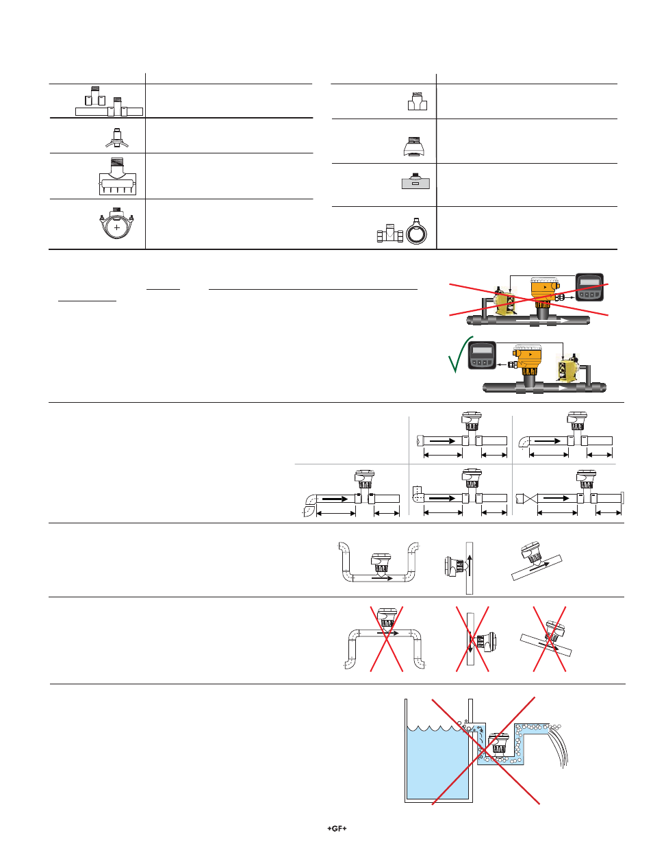
3.1 Installation: Selecting a Location
• The 2551 requires a full pipe and a fully developed turbulent À ow pro¿ le for accurate
measurement.
• If the piping system harbors air pockets or bubbles, take steps to locate the sensor so
the air pockets will not contact the electrodes.
• In vertical installations, assemble the 2551 so the conduit ports are facing downward.
This prevents condensation inside the conduit from being directed into the 2551
electronics housing.
• Chemical injection systems can temporarily alter the À uid conductivity and cause
anomalies in the magmeter measurement.
To avoid this problem, install the magmeter UPSTREAM of the injection point.
Reducer
15 x I.D.
5 x I.D.
20 x I.D.
5 x I.D.
90° Elbow
40 x I.D.
5 x I.D.
2 x 90° Elbow
3 dimensions
25 x I.D.
5 x I.D.
2 x 90° Elbow
50 x I.D.
5 x I.D.
Pump/Valve
+
GF
+
+GF+
+
GF
+
+GF
+
+GF+
OK
OK
OK
Vertical flow is OK if the pipe remains full at all times.
3. Installation: Pipe Fittings
Georg Fischer offers a wide selection of installation ¿ ttings that control the position of the Magmeter electrodes in relation to the
dimensions of the pipe. You will ¿ nd a complete list of order numbers for installation ¿ ttings in the Calibration Tables on pages 12-13.
Select a location with suf¿ cient distance
of straight pipe immediately upstream of
the sensor.
Locating the sensor in a trap or where
the À ow is upward helps to protect the
sensor from exposure to air bubbles
when the system is in operation.
These con¿ gurations are not
recommended because it is
dif¿ cult to keep the pipe full.
Type Description
• 2 to 4 inch, cut 1-7/16 inch hole in pipe
• Over 4 inch, cut 2-1/8 inch hole in pipe
• Special order 14 in. to 36 in.
• 0.5 to 2 inch versions
• MPVC or CPVC
• 2 to 4 inch, cut 1-7/16 inch hole in pipe
• 6 to 8 inch, cut 2-1/8 inch hole in pipe
• Available in 10 and 12 inch sizes only
• Cut 2-1/2 inch hole in pipe
• Weld in place using solvent cement
Iron, Carbon Steel,
316 SS
Threaded tees
Carbon steel &
stainless steel
Weld-on
Weldolets
• 2 to 4 inch, cut 1-7/16 inch hole in pipe
• Over 4 inch, cut 2-1/8 inch hole in pipe
• For pipes from DN 15 to 50 mm
• PP or PVDF
Type Description
Plastic
tees
Union Fittings and
Wafers
PVC
Clamp-on
Saddles
Iron
Strap-on
saddles
PVC
Glue-on
Saddles
• 1.5 in. to 2 in. PVDF insert
Fiberglass
tees
FPT
• 0.5 to 2 in. versions
• Mounts on threaded pipe ends
In a gravity-À ow system, the tank must be designed
so the level does not drop below the outlet.
This causes the pipe to draw air in from the tank.
If air bubbles pass across the Magmeter electrodes,
the output will become erratic.
Flow
Flow 6.25 GPM
Total 1234567.8>
ENTER
Signet Flow
Transmitter
Flow 6.25 GPM
Total 1234567.8>
ENTER
Signet Flow
Transmitter
Flow