Symptom possible cause solution – GF Signet 2551 Magmeter Flow Sensor - Display User Manual
Page 19
19
2551 Magmeter
12.3 Troubleshooting
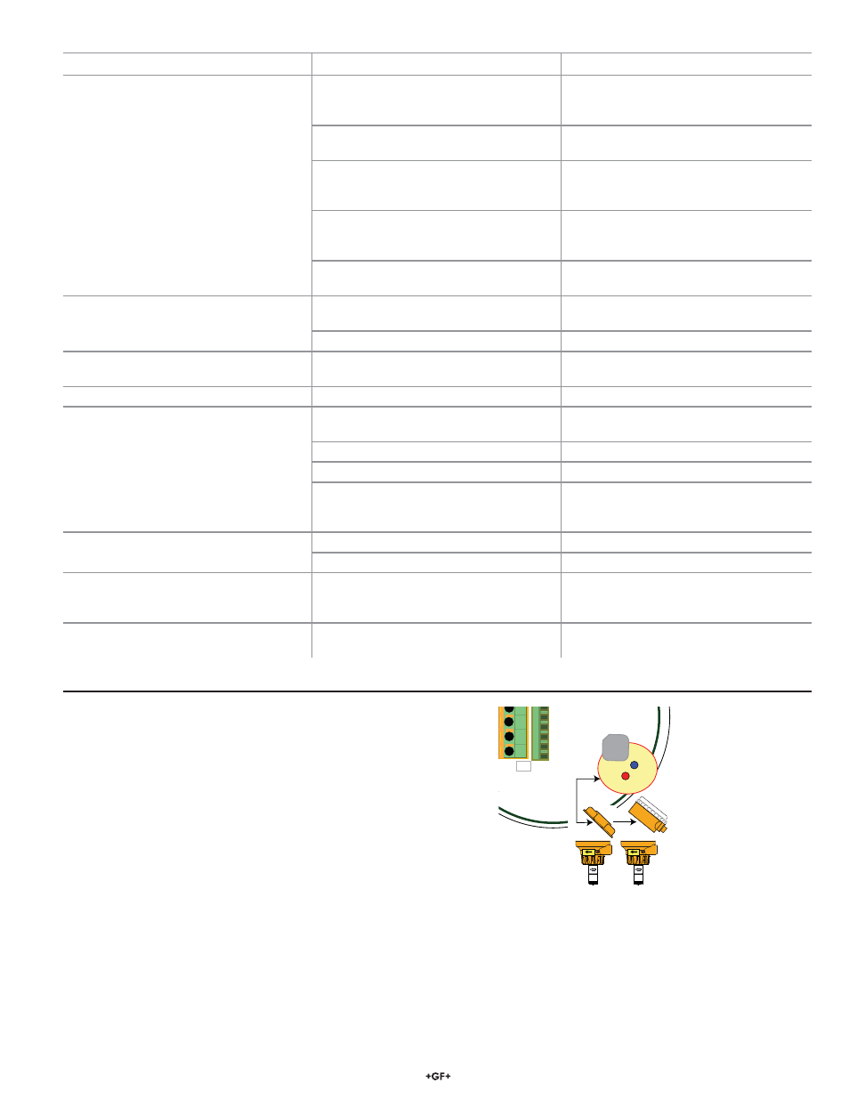
Troubleshooting with the RED and BLUE LEDs
No Lights: The power is off or the sensor is not connected
Solid Blue: The power is on but there is no À ow in the pipe.
Blinking Blue: Normal operation, blink rate is proportional to the À ow rate.
Alternating Red-Blue: Empty pipe indication (electrodes are not wet.)
Blinking Red: System errors (Electrical noise interference)
Solid Red: Instrument error (defective electronic component)
1
2
3
4
D7
D6
Flow
Flow
Reverse fl ow:
• Frequency out cannot distinguish reverse À ow from forward À ow. The output will be the absolute value.
• Digital (S
3
L) output: Reverse À ow results in 0 À ow rate displayed on 8900, or with negative numbers on the 9900.
• 4 to 20 mA output can be spanned into negative À ow range using the custom setup tool. (example: 4-20 mA = -100 to +100 GPM)
Empty Pipe Detection
• Frequency output will be locked to 0 Hz if electrodes are not wet.
• Digital (S
3
L) output will be locked to 0 if electrodes are not wet.
• 4-20 mA will be locked to 4 mA if electrodes are not wet.
• Blue and Red LED indicators on the magmeter circuit will blink alternately if the electrodes are not wet.
Symptom
Possible Cause
Solution
Output is erratic and unstable.
Magmeter installed too close to upstream
obstruction.
Relocate the magmeter to have straight
uninterrupted pipe upstream of the sensor
for at least 10 x the pipe diameter.
Magmeter located in area exposed to air
bubbles/pockets.
Eliminate air bubbles in the pipe.
Magmeter is installed in pipe backwards.
Remove the magmeter and reinstall with
the À ow direction arrow on the sensor body
pointed DOWNSTREAM.
Electrical noise is interfering with the
measurement.
Review the grounding of the magmeter and
the pipe. Install adequate Earth ground to
allow the Magmeter to operate properly.
Electrodes are coated with deposits or
chemical oxide layers.
Carefully clean the electrodes. Refer to
sensor manual for details.
Output is not 0 when À ow is stopped.
Electrodes not adequately conditioned in
À uid.
Allow the sensor to sit in full pipe for
24 hours then restart.
Fluid is moving inside the pipe.
Increase the Low Flow Cutoff. (section 7.0)
No 4 to 20 mA output.
Loop power not connected correctly.
Connect 24 VDC ±10% connected to loop
terminals 1 and 3.
4 to 20 mA current output is incorrect.
4-20 mA is not scaled properly.
Check and reset in the Setup Menu.
No Frequency output.
No S
3
L output.
2551 is wrong model.
Frequency/S
3
L model:
3-2551-21 (w/rlys) or -41 (w/o rlys).
Incorrect setting in Options Menu.
Select Frequency in the Options menu.
Wiring is not correct.
Check wiring, make corrections.
Frequency input to other manufacturer's
À ow instrument does not have pull-up
resistor.
Install 10 k resistor. (section 5.1)
No À ow rate, current output is 22 mA.
The À uid is too clean for Magmeter.
Unsuitable application for Magmeter.
Electronic component failure.
Return 2551 to factory.
Blank display, no backlighting, no relay
LEDs, but external equipment using output
signal is still working.
2551 AUX power is not connected.
Connect AUX power (section 5.5)
(9 to 24 VDC, 0.4 A max.)
Error Message:
"Error Not Saved"
Main power is below speci¿ cation.
Correct the main power de¿ ciency.