Battery installation and replacement, Wiring – GF Signet 8150 Battery-Powered Flow Totalizer User Manual
Page 4
4
8150 Flow Totalizer
5. Battery Installation and Replacement
Two 3.6 V lithium thionyl chloride batteries, AA-size (7400-0011) are installed in the Totalizer.
NOTE:
THE 8150 WILL NOT OPERATE WITH STANDARD 1.5 V ALKALINE BATTERIES.
USE 3.6 V SAFT LS14500 LITHIUM BATTERIES OR EQUIVALENT ONLY!
CAUTION
When replacing batteries,
remove and replace
one battery at a time
Remove and replace
this battery first.
1
2
3
4
5
6
Note: Lithium Batteries
Dispose of properly!
Replace with 3.6 V Lithium battery
+ +
- -
• Remove pull tabs from the batteries to power up the 8150.
• Observe polarity! Note that both batteries should face the
same direction.
• When the “low battery” indicator appears on the display, both
batteries should be replaced within 90 days.
• Remove and replace battery #1 fi rst, then remove and replace
battery #2.
This ensures that all settings and totalizer values are saved.
• If the low battery symbol reappears for more than 10 seconds
after installing new batteries, one battery is reversed, or battery
#2 was installed before battery #1.
• Secure the batteries by fastening the hook-and-loop straps.
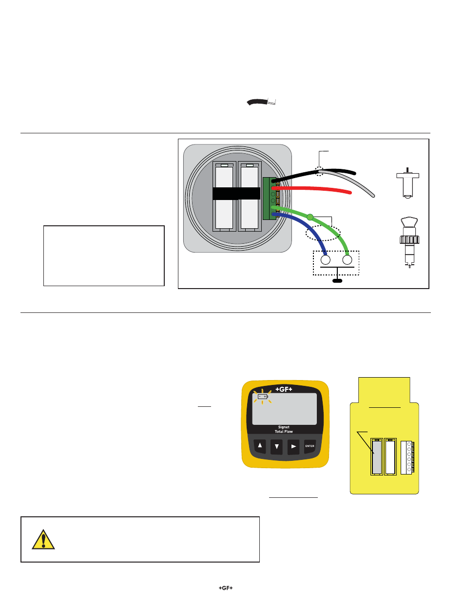
4. Wiring
• The wiring is identical for the panel mount and the fi eld mount versions of the Totalizer.
• Only one wire should be inserted into a terminal. Splice double wires outside the terminal.
• External Reset for Total #1: Use no more than 30 m (100 ft) of 2-conductor twisted-pair cable connected to a dry contact
(for example, an ordinary door-bell button or relay contact).
• Only Totalizer #1 can be reset by the external connection.
• Total #1 will not be displayed unless it is the standard totalizer selection.
Instructions
1. Remove 10 mm (
3
/
8
in.) of insulation from sensor cable conductors.
2. Press down on orange lever to open terminal.
3. Insert wire into terminal until it hits bottom.
4. Release the lever to secure wire.
10 mm
Input Wiring
Use this wiring scheme for
Signet models 515 and 525.
DISPOSE OF EXPENDED BATTERIES PROPERLY!
Lithium batteries contain hazardous chemicals.
Dispose of batteries in accordance with local regulation.
Terminal Function
1
Signal
Ground
2
Sensor
signal
3
Open Collector Signal
4
DC Power to sensor
5
Ground
6
Ext.
Reset
1
2
3
4
5
6
+
-
+
-
RED
#1 #2
Totalizer 1
Remote reset
Connect shield
to Ground wire
Splice BLK and SHLD
together outside of terminal
BLACK
SH
IE
LD
515
525
Shipping Notice:
If the battery pull tabs have been removed, remove the batteries from the totalizer prior to shipping.
Dispose of the batteries in accordance with the local regulations.