Panel cutout, Panel mount installation detail – GF Signet 8150 Battery-Powered Flow Totalizer User Manual
Page 3
3
8150 Flow Totalizer
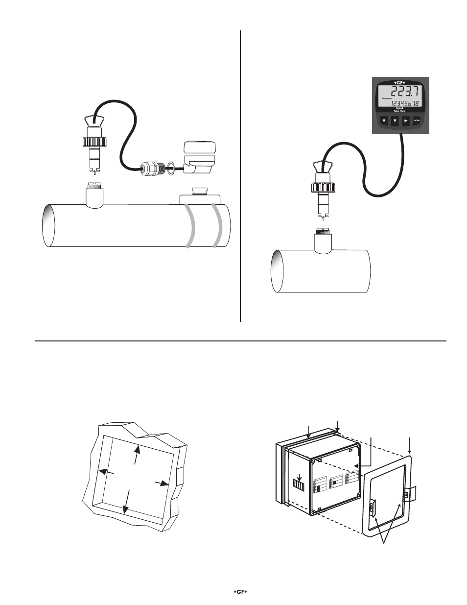
92 x 92 mm
(3.62 x 3.62 in.)
Panel cutout
Output -
Output +
System Pwr
Loop -
System Pwr
Loop +
2
1
4
3
Sensr Gnd
(SHIELD)
Sen
sr IN
(RED)
Sensr V+
(BLACK)
7
6
5
quick-clips
gasket
panel
terminals
mounting
bracket
latch
Panel Mount
Installation Detail
• The 8150-1P panel mount Totalizer is a standard ¼ DIN package. Use a 92 × 92 mm punch tool to make the panel cutout.
• Minimum spacing of 25 mm (1 in.) between panel units is recommended.
3.7 Panel Mount Installation Detail
3.5 Remote Field mount on Pipe
3.6 Remote Installation with Panel Mount Totalizer
The parts identifi ed in bold type are required for this installation.
Other parts are shown for reference only.
The parts identifi ed in bold type are required for this installation.
Other parts are shown for reference only.
Use 2-conductor shielded cable no more than 30 m (100 ft) long.
Flow
Totalizer
(3-8150-1)
Signet
Fittings
Standard Mount
Paddlewheel
(P51530-X)
Universal Mounting Kit
(3-8050)
NOTE: Pipe straps
not included
Totalizer
Panel Mount
(3-8150-1P)
Signet
Fittings
Standard Mount
Paddlewheel
(P51530-X)