Models 5800-s, Installation and operation manual – Brooks Instrument 5800S Series User Manual
Page 18
Installation and Operation Manual
X-TMF-5800S-MFC-eng
PN 541-C-051-AAG
November, 2008
Models 5800-S
18
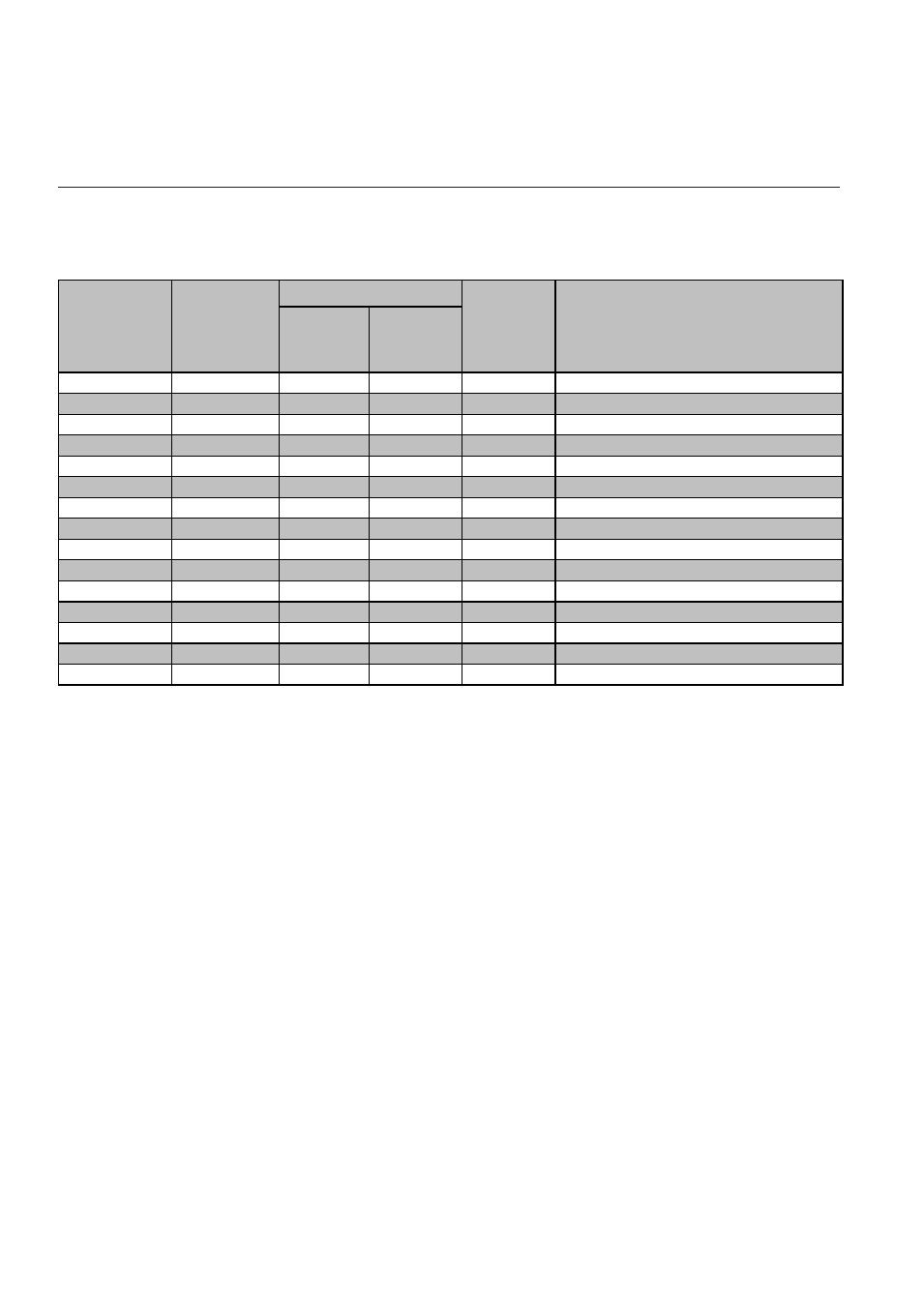
Table 2-3: Electrical interfacing. Smart TMF cable
sub D (25p)
female
pin no.
sub D (9p)
female
pin no.
1.
6
brown
Setpoint return (-)
2.
10
white
0 (1)-5 Vdc Flow signal output
3.
9
grey/pink
(TTL) Open collector alarm output
4.
2
red/blue
0 (4)-20 mA Flow signal output
5.
13
red
+15 Vcc to +28 Vdc Power supply
6.
14
blue
-15 Vdc Power supply (if required)
7.
3
violet
0 (4)-20 mA Setpiont input (+)
8.
5
grey
0 (1)-5 Vdc Setpiont input (+)
9.
12
7
5
black
Power supply common
10.
8
pink
Flow signal output common
11.
4
yellow
+5 Vdc ref. output
12.
7
green
valve override input
11
shielding
Chassis
14.
2
3
green/white Optional RS232C-RxD or RS485-A-
15.
3
2
blue/white
Optional RS232C-TxD or RS485-A+
Read-out side
sub D (15p)
male
pin no.
Sub-D (15 c.)
sub D (15p)
female
pin no.
Colour
Function
Computer side
Section 2: Installation
- QMBC (52 pages)
- SolidSense II (28 pages)
- SLA7810/20 (36 pages)
- SLA5810/20 (50 pages)
- SLA5840 (46 pages)
- SLA7840 (40 pages)
- 5866E (65 pages)
- IPS122 2 Indicating Pressure Switches" (18 pages)
- IPT122 2 Indicating Pressure Transmitters" (22 pages)
- 8601 (20 pages)
- PTI Metal Seal Mass Flow Controller w/Real-Time Flow Error Detection & Advanced Diagnostics (82 pages)
- SLA5800 Series (76 pages)
- 4800 Series (50 pages)
- 5850EM (74 pages)
- 5851EM (62 pages)
- 5850E (64 pages)
- 5851E (64 pages)
- 5860E (46 pages)
- 5861E (44 pages)
- 5850i (62 pages)
- 5851i (62 pages)
- 5860i (48 pages)
- 5861i (48 pages)
- 5881/91 (40 pages)
- GF40 (78 pages)
- SLAMf Series (76 pages)
- Mfi Series (82 pages)
- 0254 (124 pages)
- 0260 (14 pages)
- CMC Series (36 pages)
- XacTorr CMX45 (64 pages)
- MT3809G (78 pages)
- MT3809E (72 pages)
- MT3810 (66 pages)
- 3600 Series (56 pages)
- 3750 (64 pages)
- Control Valve (16 pages)
- GT1000 (52 pages)
- 1100 Series (52 pages)
- 1307 (18 pages)
- 1358 (44 pages)
- 1350 (46 pages)
- 1250 (2 pages)
- FC8800 Series (48 pages)