9 digital communication, Models 5800-s – Brooks Instrument 5800S Series User Manual
Page 13
Models 5800-S
Installation and Operation Manual
X-TMF-5800S-MFC-eng
PN 541-C-051-AAG
November, 2008
13
common) on the D-connector. If a -15 Vdc power supply is required, pin 6 must
be connected and jumper [K2] on the p.c. board must be set the lower
position
(see Figure 2-2).
This is applicable for model 5851S and/or when a Normally Opened (N.O.)
control valve is used.
NOTE: With regard to the power supply connections, the attached cable must
be as short as possible to ensure that the minimum required voltage and
current is available at the mass flow device.
Cable Shielding Earth
Cable requirements
Compliance with EMC directive 89/336/EEC, requires that the equipment be
fitted with fully screened signal cables with at least 80% shielding.The cable
shielding should be connected to the PG connector’s metal shell, and have
360° shielding at both ends. The shielding should be connected to an earth
terminal.
For translations of this instruction, see Appendix D: Translations of installation
instructions
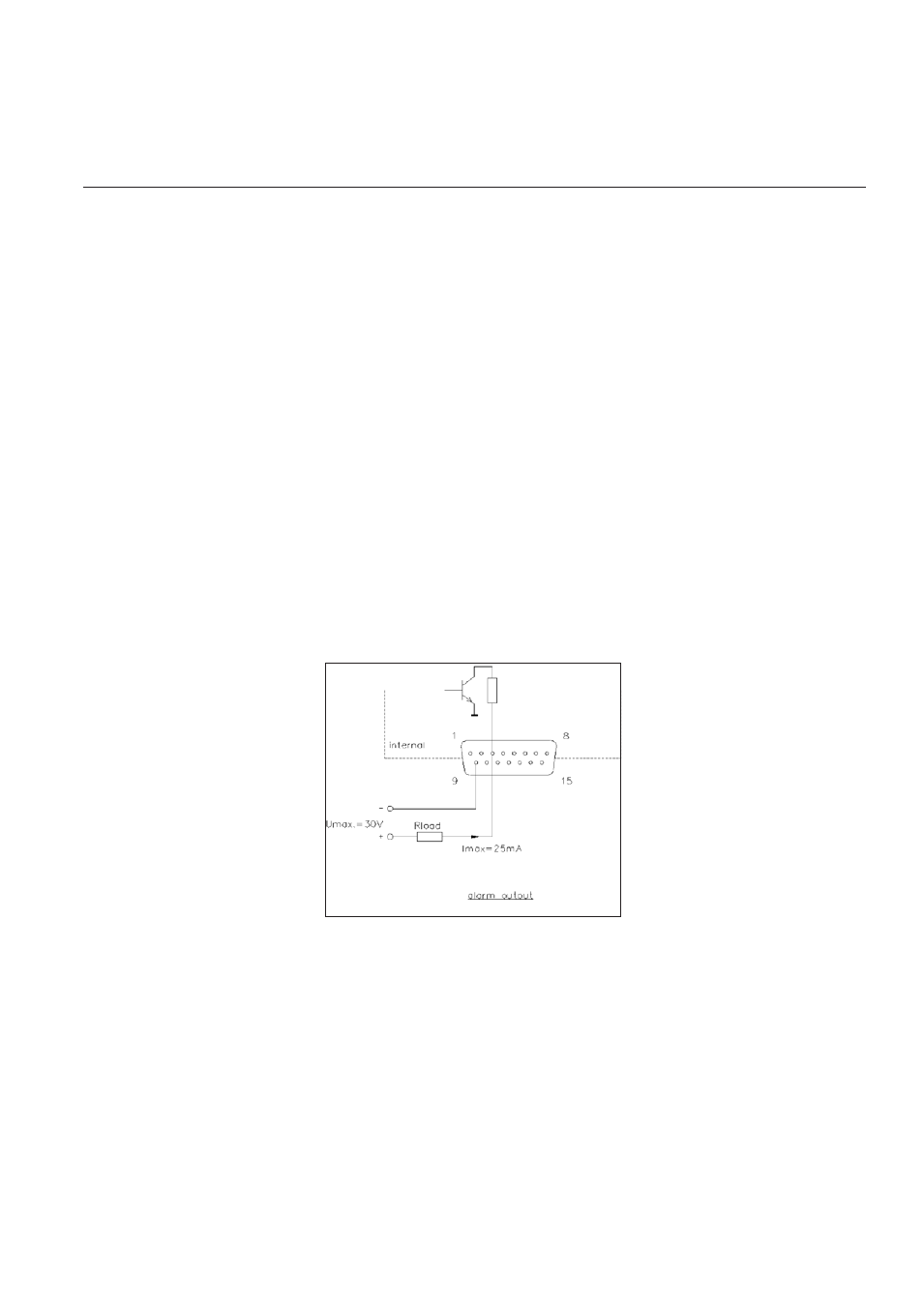
Alarm (pin 3 of 9)
A (TTL) Open Collector alarm output is available.
Type of used transistor is NPN.
Figure 2-1: Open Collector
Valve override (pin 12; Controller models only)
To open or close the control valve independently of the Set point signal (e.g. for
safety reasons), pin 12 is available to carry a valve override signal. Leave floating
(i.e. not connected) to allow for normal control operation.
≥ 5 Vdc
Valve Open (for both NO and NC valves)
≤
≤
≤
≤
≤ 0 Vdc
Valve Closed (for both NO and NC valves)
NOTE: The valve override command on pin 12 takes precedence over the
communication-mediated valve override command.
Digital communication (pins 14 and 15)
Section 2: Installation